exercises · South Africa
PLC motor jog circuit vs latched run, explained
Build a PLC motor jog circuit alongside a latched run on one output: mode selector, seal-in isolation, and the classic jog-latches-anyway bug to avoid.
06 / visual field notes
Visual guide
6 original technical diagrams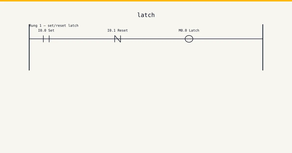
Difficulty: beginner · 20–40 minutes
This is a build-along exercise, not a reading page. You get a short job card of the kind a contractor actually receives, an I/O table to wire against, and a worked solution to check yourself with once your own version runs — plus the test sequence that proves it, because a program you haven't tried to break is a program you haven't tested. Sketch first, build second, test third. Same order as on site.
Open the simulator and build along →The job card
Job card: the millwright at a Vereeniging steel service centre needs to inch the slitter take-up conveyor to align a coil — a second or two of movement at a time, motor running only while the button is held. Production needs the same conveyor latched on for normal running. The panel gets a two-position selector (RUN/JOG), a start button, a jog button and a stop button, all driving one motor output. In JOG the start button must do nothing and the motor must never latch. In RUN the jog button must do nothing. The stop button kills the motor in either mode. Simple spec — and the standard place where the seal-in bites people who wire the jog button into the wrong branch.
Read it the way a foreman hands it to you. Every requirement on that card is a test case: when you think the program is done, walk the card line by line and force each condition in the watch table. Any line without a matching test you actually ran means you're not done yet. That habit — card in one hand, watch table in the other — is what separates a programmer who commissions clean from one who gets the call-back at month end.
I/O assignment
Wire your simulator project to this table exactly. Half the value of an exercise like this is tag discipline: name the points the same way the table does and the solution steps further down will read straight onto your rungs without translation.
| Tag | Type | Address | Purpose |
|---|---|---|---|
ModeRun | DI | %I0.0 | Two-position selector switch. TRUE = RUN mode (latched), FALSE = JOG mode. |
StartPB | DI | %I0.1 | Start pushbutton, normally open, momentary. Active in RUN mode only. |
JogPB | DI | %I0.2 | Jog pushbutton, normally open, momentary. Active in JOG mode only. |
StopPB | DI | %I0.3 | Stop pushbutton, normally closed, wired fail-safe. TRUE = healthy and unpressed. Effective in both modes. |
Motor | DO | %Q0.0 | Take-up conveyor motor contactor coil. |
A note on the Type column: DI is a digital input, DO a digital output, AI and AO are analogue in and out, and M is an internal memory bit that never leaves the CPU. The addresses use IEC notation (%I, %Q, %M). If your head is in Allen-Bradley land, map %I0.0 to I:0/0 and carry on — the logic doesn't change, only the spelling of the addresses.
Think before you build
Don't open the ladder editor yet. The notes below are the design decisions that determine whether your program works first time or fights you for an hour. Read them, then sketch the rung shapes on paper. Pencil and the back of a delivery note is fine — most working programs start exactly there.
- Keep the latch and the jog in separate rungs and OR them at the motor output. The whole bug class in this exercise comes from putting JogPB inside or parallel to the seal-in branch, where the sealed contact happily latches a jog you meant to last half a second.
- Seal the internal Latched bit, not the Motor output. If the seal contact is the motor output itself, a jog pulse feeds the seal branch and the jog latches — the most reported 'ghost start' in beginner programs.
- Decide what happens if the selector flips mid-motion. Moving RUN to JOG while latched should drop the latch (the millwright flipping to JOG wants control, not a runaway); the ModeRun contact inside the latch rung gives you that for free.
Step-by-step solution
Build one rung at a time and test after every rung. Never write the whole program and then test the lot — when five rungs go in untested and the machine misbehaves, you're debugging five suspects instead of one. The steps below follow that order. In the pseudo-rungs, ] [ is a normally-open examine, ]/[ is normally-closed, and ( ) is the output coil.
Rung 1: the latched run path
Seal-in on an internal Latched bit, gated by ModeRun: (StartPB OR Latched) AND ModeRun AND StopPB. With ModeRun inside the rung, flipping the selector to JOG breaks the latch immediately, and starting is only possible in RUN mode.
// ──┬──[ ]StartPB──┬──[ ]ModeRun──[ ]StopPB──( )Latched
//   └──[ ]Latched──┘
Rung 2: the jog path
No seal anywhere near it: NOT ModeRun AND JogPB AND StopPB drives a Jogging bit. The motor follows the button level exactly — press, it turns; release, it stops on the spot. That direct mechanical feel is the entire point of jog.
// [/]ModeRun──[ ]JogPB──[ ]StopPB──( )Jogging
Rung 3: combine at the output
Motor is Latched OR Jogging — one coil, one rung, two clearly separated sources. Anyone reading the program later sees instantly which path energised the motor, which matters when the question is 'why did it move'.
// ──┬──[ ]Latched──┬──( )Motor
//   └──[ ]Jogging──┘
Test the cross-mode cases
In RUN: start, release, motor holds; stop kills it. In JOG: hold jog, motor runs; release, it stops with no latching — hammer the jog button ten times fast and confirm the motor never holds in. Now the cross cases everyone skips: press jog in RUN mode (nothing), press start in JOG mode (nothing), and flip the selector from RUN to JOG while latched — the motor must stop, not transfer into a phantom jog.
The structured text version
The same logic in IEC 61131-3 structured text — each output written as a boolean equation you can read aloud.
(* Jog vs latched run on one motor, IEC 61131-3 ST *)
Latched := (StartPB OR Latched) AND ModeRun AND StopPB;
Jogging := NOT ModeRun AND JogPB AND StopPB;
Motor   := Latched OR Jogging;
Ladder wins this argument when an electrician has to fault-find your program at 02:00 with a multimeter mindset — the rung looks like the circuit diagram it replaced, and that familiarity is worth real money on a breakdown. ST starts winning when the pattern repeats: ten pumps with the same interlock shape is one ST function called ten times, where ladder hands you ten near-identical rungs to keep in sync by hand forever. Learn both. Build the exercise in ladder first, then write the ST version and confirm the two behave identically in the simulator. That translation skill — same logic, two languages — is exactly what technical interviews and commissioning work both test.
Common mistakes
Every mistake below comes from a real program: either one of ours from years back, or one we were called in to fix. Check your build against the list before you call the exercise done.
- Wiring JogPB in parallel with StartPB inside the seal circuit. The jog pulse energises the coil, the coil's own seal contact closes, and the 'half-second nudge' becomes a latched run — with the millwright's hands near a coil of steel strip.
- Sealing through the motor output instead of a dedicated Latched bit. The jog rung drives the same output, the output's contact feeds the seal branch, and jog latches by the back door even though the jog rung itself contains no seal.
- Leaving ModeRun out of the latch rung. The conveyor is latched, someone flips to JOG to make an adjustment, and the latch keeps driving the motor underneath the jog logic — two sources fighting for one output.
- Testing each mode in isolation and never the transitions. Every reported failure of this circuit in the field happens at a mode change or a button overlap, exactly the cases a two-minute test plan covers and a casual test does not.
Most of these share one root cause: the rung shape doesn't match the intent, so the program passes the obvious test and fails the edge case. That's why the solution steps force the edge cases deliberately instead of stopping at "it starts and it stops". Steal that habit for every program you write from here on.
Take it further
Got it working first time? Good — now make it earn its keep. Each extension below changes the spec the way a real client does: after you've finished. Treat each one as a fresh job card, and re-test the whole program afterwards, not just the new part. Regressions hide in the rungs you didn't touch.
- Add a 200 ms TOF on the jog output so each press gives a minimum controllable nudge even from a feather-tap — then argue with yourself about whether that defeats the purpose of jog.
- Add forward and reverse jog with mutual interlock and a 500 ms direction-change dead time — the contactor interlocking logic from the star-delta exercise applies directly.
- Add the 3-second pre-start horn from the conveyor exercise to the RUN path only, and decide explicitly why jog should (or should not) skip the horn. Writing that justification down is the real exercise.
If you build even one extension, screenshot the finished rungs and keep them somewhere organised. A folder of working, tested exercise solutions is the start of a portfolio — and hiring engineers ask candidates to explain a rung far more often than they ask to see certificates.
Run this in the simulator
Every beginner exercise on this site, this one included, runs on the simulator's free tier — no card details, no install, signed up and on a rung inside two minutes. The watch table is the part that matters here: force the inputs, watch the outputs, and run the test sequence from the solution steps against a live scan cycle instead of imagining it. The full curriculum — the structured version of these exercises with feedback on every submission — plus the wiring track, sensor school and cert packs sit in the Basic tier at USD 12 per month and Pro at USD 29 per month. Training centres and engineering departments wanting this in a lab should look at the Teams tier (USD 199 per seat per year, minimum 5 seats); the training-centres page carries the institutional details and the contact form. If you're an individual learning the trade, start on the free tier, finish the beginner set, and decide from there.
Run this exercise on the free tier →Reference
Ladder logic on Wikipedia covers the background theory behind this exercise, and it's worth twenty minutes of your time after the build — theory sticks better once your hands have done the work. The languages used here are defined by the IEC 61131-3 standard from iec.ch, and your CPU vendor's manual remains the canonical source for how a specific controller executes them.
What we don't claim
This site is not SAQA-registered, not MerSETA-accredited, and not an NQF-registered qualification provider. Our completion certificates are course-level only — they describe what you covered, not an NQF Level X qualification. The CCST cert from ISA is the portable industry credential we recommend; we are not an ISA cert delivery partner either, but our cert packs are CCST-aligned. The exercise on this page is practice material written by working programmers: finishing it proves the skill to yourself and to the simulator's progress tracking, not to a regulator.