exercises · South Africa
Start-stop seal-in: PLC exercises for beginners
Build the classic start-stop seal-in motor circuit: full I/O list, rung-by-rung ladder steps, a structured text version, and the mistakes that bite hard.
06 / visual field notes
Visual guide
6 original technical diagrams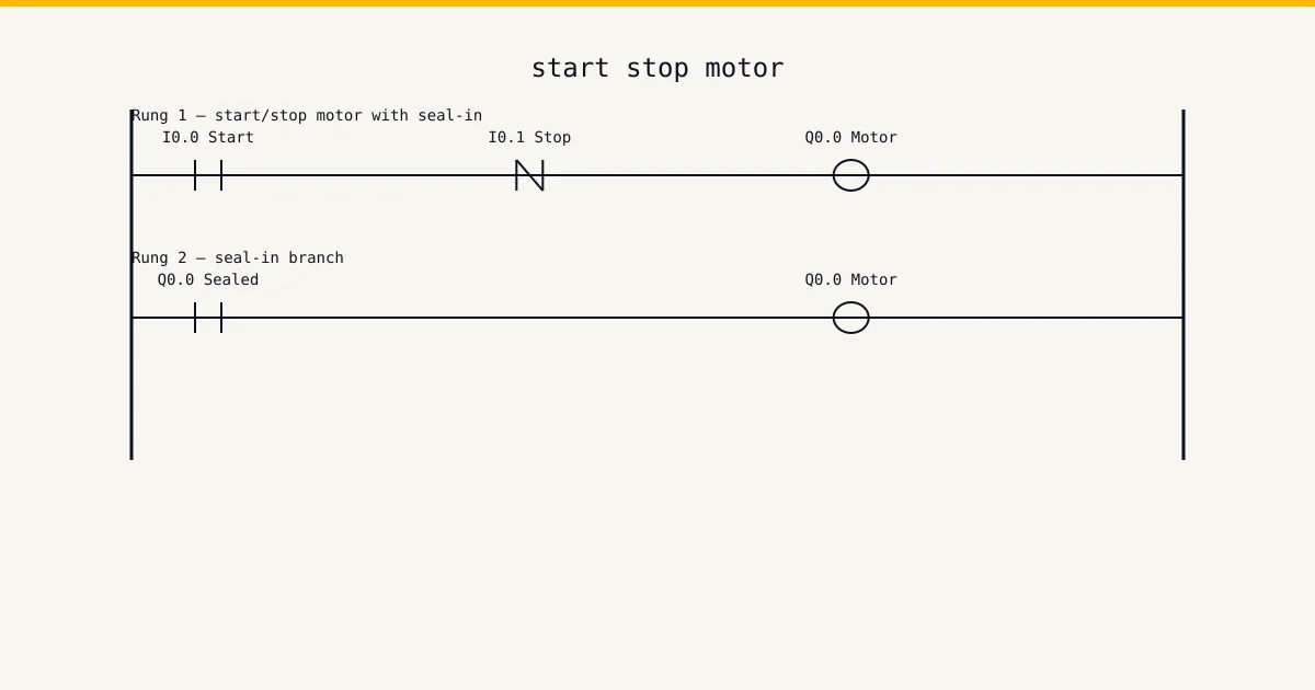

Difficulty: beginner · 20–40 minutes
This is a build-along exercise, not a reading page. You get a short job card of the kind a contractor actually receives, an I/O table to wire against, and a worked solution to check yourself with once your own version runs — plus the test sequence that proves it, because a program you haven't tried to break is a program you haven't tested. Sketch first, build second, test third. Same order as on site.
Open the simulator and build along →The job card
Job card: the extraction fan above the shrink-wrap tunnel on a Joburg packaging line currently runs off a contactor that someone has wedged in with a cable tie. Production wants a proper start-stop station on the panel door: green button to start, red button to stop, and the fan must drop out if the thermal overload trips. The fan must NOT restart on its own when power comes back after load-shedding — an operator has to press start again. You have a spare PLC in the panel with three inputs and two outputs free. Wire it, program it, prove it.
Read it the way a foreman hands it to you. Every requirement on that card is a test case: when you think the program is done, walk the card line by line and force each condition in the watch table. Any line without a matching test you actually ran means you're not done yet. That habit — card in one hand, watch table in the other — is what separates a programmer who commissions clean from one who gets the call-back at month end.
I/O assignment
Wire your simulator project to this table exactly. Half the value of an exercise like this is tag discipline: name the points the same way the table does and the solution steps further down will read straight onto your rungs without translation.
| Tag | Type | Address | Purpose |
|---|---|---|---|
StartPB | DI | %I0.0 | Green start pushbutton, normally open, momentary. TRUE only while pressed. |
StopPB | DI | %I0.1 | Red stop pushbutton, normally closed and wired fail-safe. The input reads TRUE while the circuit is healthy and the button is unpressed; pressing it (or a broken wire) drops the input to FALSE. |
OverloadOK | DI | %I0.2 | Thermal overload relay auxiliary contact, normally closed, wired fail-safe. TRUE means the overload has not tripped. |
FanRun | DO | %Q0.0 | Contactor coil for the extraction fan motor, 230 V AC via interposing relay. |
RunLamp | DO | %Q0.1 | Green running lamp on the panel door, follows the fan contactor. |
A note on the Type column: DI is a digital input, DO a digital output, AI and AO are analogue in and out, and M is an internal memory bit that never leaves the CPU. The addresses use IEC notation (%I, %Q, %M). If your head is in Allen-Bradley land, map %I0.0 to I:0/0 and carry on — the logic doesn't change, only the spelling of the addresses.
Think before you build
Don't open the ladder editor yet. The notes below are the design decisions that determine whether your program works first time or fights you for an hour. Read them, then sketch the rung shapes on paper. Pencil and the back of a delivery note is fine — most working programs start exactly there.
- Stop and overload are normally-closed in the field, so a healthy circuit feeds the PLC a TRUE. In the ladder you therefore use a normally-open contact for each — the wiring already did the inversion. This trips up almost everyone the first time.
- Use a seal-in contact, not a SET/RESET latch. A seal-in drops dead the moment power blips, which is exactly the restart behaviour the job card asks for. A latch bit can be retentive and would restart the fan unattended after load-shedding.
- The seal-in branch goes around the start button only — never around the stop or overload contacts. Anything inside the seal loop can no longer break the circuit.
Step-by-step solution
Build one rung at a time and test after every rung. Never write the whole program and then test the lot — when five rungs go in untested and the machine misbehaves, you're debugging five suspects instead of one. The steps below follow that order. In the pseudo-rungs, ] [ is a normally-open examine, ]/[ is normally-closed, and ( ) is the output coil.
Rung 1: the start path
Drop a normally-open contact for StartPB in series with normally-open contacts for StopPB and OverloadOK, feeding the FanRun coil. Press start and the fan runs — but only while your finger is on the button. That is the half-built circuit; the seal-in fixes it next.
// Rung 1 (incomplete)
// StartPB ──[ ]──[ ]StopPB──[ ]OverloadOK──( )FanRun
Rung 1: add the seal-in branch
Add a normally-open FanRun contact in parallel with StartPB only. Once the coil energises, its own contact holds the rung true after you release the button. StopPB and OverloadOK stay outside the branch so either can still break the circuit.
// Rung 1 (complete)
// ──┬──[ ]StartPB──┬──[ ]StopPB──[ ]OverloadOK──( )FanRun
//   └──[ ]FanRun───┘
Rung 2: the run lamp
One rung: a normally-open FanRun contact driving the RunLamp coil. Keep indication on its own rung rather than a second coil on the same output — two coils writing one output is a classic scan-order bug.
// Rung 2
// FanRun ──[ ]──( )RunLamp
Test it properly
Download, then force the inputs in your simulator: press start, release, confirm the fan holds in. Press stop — it must drop instantly. Now the test most people skip: with the fan running, force OverloadOK to FALSE and confirm the fan drops and stays off when the overload resets. Finally cycle PLC power mid-run: the fan must stay off until start is pressed again.
The structured text version
The same logic in IEC 61131-3 structured text — each output written as a boolean equation you can read aloud.
(* Start-stop seal-in, IEC 61131-3 ST *)
(* StopPB and OverloadOK are NC in the field: TRUE = healthy *)
FanRun  := (StartPB OR FanRun) AND StopPB AND OverloadOK;
RunLamp := FanRun;
Ladder wins this argument when an electrician has to fault-find your program at 02:00 with a multimeter mindset — the rung looks like the circuit diagram it replaced, and that familiarity is worth real money on a breakdown. ST starts winning when the pattern repeats: ten pumps with the same interlock shape is one ST function called ten times, where ladder hands you ten near-identical rungs to keep in sync by hand forever. Learn both. Build the exercise in ladder first, then write the ST version and confirm the two behave identically in the simulator. That translation skill — same logic, two languages — is exactly what technical interviews and commissioning work both test.
Common mistakes
Every mistake below comes from a real program: either one of ours from years back, or one we were called in to fix. Check your build against the list before you call the exercise done.
- Drawing the seal-in branch around the stop contact as well as the start button. The circuit then ignores the stop button completely once running — the seal path bypasses it every scan.
- Using a normally-closed contact in the logic for the NC-wired stop button. That is a double inversion: the rung is blocked while the system is healthy and the motor can only run while someone holds the stop button in.
- Building it with SET and RESET coils instead of a seal-in. The latch bit survives a power dip in most PLCs, so after load-shedding the fan restarts with nobody near the machine.
- Never testing the broken-wire case. Pull the stop button wire off the terminal: with fail-safe NC wiring the fan must stop. If your logic needed a NO stop button, the broken wire would be invisible until the day the button does nothing.
Most of these share one root cause: the rung shape doesn't match the intent, so the program passes the obvious test and fails the edge case. That's why the solution steps force the edge cases deliberately instead of stopping at "it starts and it stops". Steal that habit for every program you write from here on.
Take it further
Got it working first time? Good — now make it earn its keep. Each extension below changes the spec the way a real client does: after you've finished. Treat each one as a fresh job card, and re-test the whole program afterwards, not just the new part. Regressions hide in the rungs you didn't touch.
- Add a jog mode on a spare input: motor runs only while the button is held, with no seal-in. Getting jog and latched run to share one motor output cleanly is the next exercise up.
- Add a 3-second start-warning horn before the contactor pulls in, the way the conveyor exercise does it — one TON and one extra output.
- Add a motor-running feedback input from the contactor's aux contact and alarm if the coil is on but the feedback stays off for more than 2 seconds.
If you build even one extension, screenshot the finished rungs and keep them somewhere organised. A folder of working, tested exercise solutions is the start of a portfolio — and hiring engineers ask candidates to explain a rung far more often than they ask to see certificates.
Run this in the simulator
Every beginner exercise on this site, this one included, runs on the simulator's free tier — no card details, no install, signed up and on a rung inside two minutes. The watch table is the part that matters here: force the inputs, watch the outputs, and run the test sequence from the solution steps against a live scan cycle instead of imagining it. The full curriculum — the structured version of these exercises with feedback on every submission — plus the wiring track, sensor school and cert packs sit in the Basic tier at USD 12 per month and Pro at USD 29 per month. Training centres and engineering departments wanting this in a lab should look at the Teams tier (USD 199 per seat per year, minimum 5 seats); the training-centres page carries the institutional details and the contact form. If you're an individual learning the trade, start on the free tier, finish the beginner set, and decide from there.
Run this exercise on the free tier →Reference
Ladder logic on Wikipedia covers the background theory behind this exercise, and it's worth twenty minutes of your time after the build — theory sticks better once your hands have done the work. The languages used here are defined by the IEC 61131-3 standard from iec.ch, and your CPU vendor's manual remains the canonical source for how a specific controller executes them.
What we don't claim
This site is not SAQA-registered, not MerSETA-accredited, and not an NQF-registered qualification provider. Our completion certificates are course-level only — they describe what you covered, not an NQF Level X qualification. The CCST cert from ISA is the portable industry credential we recommend; we are not an ISA cert delivery partner either, but our cert packs are CCST-aligned. The exercise on this page is practice material written by working programmers: finishing it proves the skill to yourself and to the simulator's progress tracking, not to a regulator.