exercises · South Africa
PLC tank level control example with two probes
A PLC tank level control example using two probes for hysteresis: fill pump start-stop band, dry-run protection and a low-level alarm, ladder and ST code.
06 / visual field notes
Visual guide
6 original technical diagrams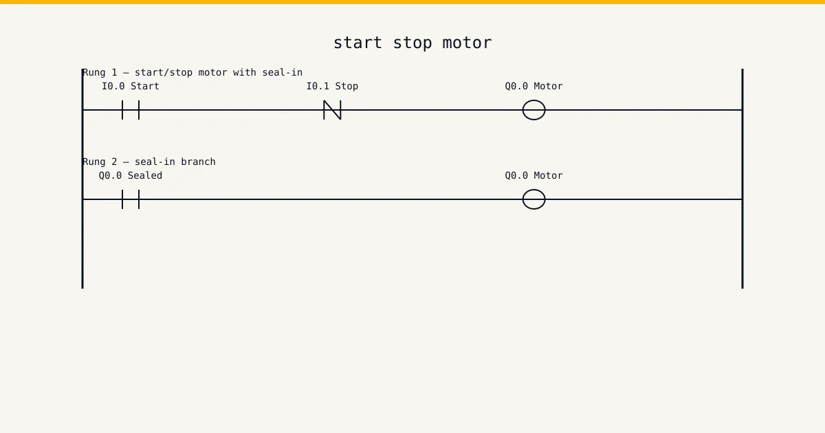
Difficulty: intermediate · 45–75 minutes
This is a build-along exercise, not a reading page. You get a short job card of the kind a contractor actually receives, an I/O table to wire against, and a worked solution to check yourself with once your own version runs — plus the test sequence that proves it, because a program you haven't tried to break is a program you haven't tested. Sketch first, build second, test third. Same order as on site.
Open the simulator and build along →The job card
Job card: the rinse-water tank for the CIP set at a KZN dairy keeps running dry mid-wash because the transfer pump only starts when someone notices the sight glass. Two conductive probes are already fitted — one at 40%, one at 90% — plus a pressure switch on the supply line. Make the fill pump start when the level drops below the low probe and run until the high probe is covered, so the pump cycles a few times an hour instead of chattering on every ripple. If supply pressure is lost the pump must stop immediately, and if the tank stays below the low probe for more than 60 seconds with the pump running, raise an alarm because something is wrong upstream.
Read it the way a foreman hands it to you. Every requirement on that card is a test case: when you think the program is done, walk the card line by line and force each condition in the watch table. Any line without a matching test you actually ran means you're not done yet. That habit — card in one hand, watch table in the other — is what separates a programmer who commissions clean from one who gets the call-back at month end.
I/O assignment
Wire your simulator project to this table exactly. Half the value of an exercise like this is tag discipline: name the points the same way the table does and the solution steps further down will read straight onto your rungs without translation.
| Tag | Type | Address | Purpose |
|---|---|---|---|
LevelLow | DI | %I0.0 | Conductive probe at 40% height. TRUE while water covers the probe. |
LevelHigh | DI | %I0.1 | Conductive probe at 90% height. TRUE while water covers the probe. |
SupplyOK | DI | %I0.2 | Supply-line pressure switch, normally closed, wired fail-safe. TRUE = pressure present; a lost supply or a broken wire both read FALSE. |
FillPump | DO | %Q0.0 | Transfer pump contactor, 3 kW centrifugal pump. |
LowAlarm | DO | %Q0.1 | Panel alarm lamp: tank below low probe for 60 s despite the pump running. |
A note on the Type column: DI is a digital input, DO a digital output, AI and AO are analogue in and out, and M is an internal memory bit that never leaves the CPU. The addresses use IEC notation (%I, %Q, %M). If your head is in Allen-Bradley land, map %I0.0 to I:0/0 and carry on — the logic doesn't change, only the spelling of the addresses.
Think before you build
Don't open the ladder editor yet. The notes below are the design decisions that determine whether your program works first time or fights you for an hour. Read them, then sketch the rung shapes on paper. Pencil and the back of a delivery note is fine — most working programs start exactly there.
- Two probes give you hysteresis for free: start below the low one, stop at the high one, and the 50% band between them sets the cycle rate. One probe with start-and-stop on the same point would chatter the contactor on every ripple — that band is the entire point of this exercise.
- The pump's seal-in holds between the probes. When the level sits between low and high, both 'start' and 'stop' conditions are false, and only the sealed bit knows whether the pump is mid-fill or mid-drain. Get the seal logic wrong and the pump state between probes is a coin toss.
- Sanity-check the probes against each other: LevelHigh TRUE while LevelLow is FALSE is physically impossible — water cannot cover the 90% probe without covering the 40% one. That combination means a probe or cable fault and is worth its own alarm.
Step-by-step solution
Build one rung at a time and test after every rung. Never write the whole program and then test the lot — when five rungs go in untested and the machine misbehaves, you're debugging five suspects instead of one. The steps below follow that order. In the pseudo-rungs, ] [ is a normally-open examine, ]/[ is normally-closed, and ( ) is the output coil.
Rung 1: the hysteresis seal-in
FillPump starts when the low probe uncovers (NOT LevelLow), seals in through its own contact, and breaks when the high probe covers (NOT LevelHigh in series) or supply pressure drops. Read it twice: the start condition is the inverted low probe, the stop condition is the high probe — the band between them is held purely by the seal.
// ──┬──[/]LevelLow───┬──[/]LevelHigh──[ ]SupplyOK──( )FillPump
//   └──[ ]FillPump───┘
Rung 2: the 60-second low-level watchdog
TON tLowWatch with IN of FillPump AND NOT LevelLow and PT of T#60s. The pump running flat out for a minute without even reaching the low probe means a shut valve, a dry supply, or an airlocked pump — the alarm output follows the done bit.
// FillPump AND NOT LevelLow ──[TON tLowWatch, PT := T#60s]
// tLowWatch.Q ──( )LowAlarm
Rung 3: probe plausibility check
LevelHigh AND NOT LevelLow is the impossible state — flag it into the same alarm output or a second lamp. Conductive probes scale up and cables get pinched; the controller noticing a lying sensor is the difference between this exercise and the toy version.
// LevelHigh AND NOT LevelLow ──( )ProbeFault
Test the band and the failure modes
In the simulator, walk the level down: pump must start only when LevelLow drops, not before. Walk it up: pump must hold in past the low probe and stop only at the high probe. Park the level mid-band and confirm the pump state depends on direction of travel — that is hysteresis working. Then force SupplyOK FALSE mid-fill (instant stop), and hold the level below low with the pump on for 61 seconds (alarm). Finally force the impossible probe combination and confirm the fault shows.
The structured text version
The same logic in IEC 61131-3 structured text — each output written as a boolean equation you can read aloud.
(* Two-probe tank level control, IEC 61131-3 ST *)
FillPump := (NOT LevelLow OR FillPump) AND NOT LevelHigh AND SupplyOK;
tLowWatch(IN := FillPump AND NOT LevelLow, PT := T#60s);
LowAlarm   := tLowWatch.Q;
ProbeFault := LevelHigh AND NOT LevelLow;
Ladder wins this argument when an electrician has to fault-find your program at 02:00 with a multimeter mindset — the rung looks like the circuit diagram it replaced, and that familiarity is worth real money on a breakdown. ST starts winning when the pattern repeats: ten pumps with the same interlock shape is one ST function called ten times, where ladder hands you ten near-identical rungs to keep in sync by hand forever. Learn both. Build the exercise in ladder first, then write the ST version and confirm the two behave identically in the simulator. That translation skill — same logic, two languages — is exactly what technical interviews and commissioning work both test.
Common mistakes
Every mistake below comes from a real program: either one of ours from years back, or one we were called in to fix. Check your build against the list before you call the exercise done.
- Starting and stopping on the same probe. The pump starts when the probe uncovers, the inflow splashes the probe, the pump stops, the splash drains, the pump starts — contactor chatter measured in cycles per minute until the contactor welds.
- Inverting the probe sense. 'TRUE when covered' versus 'TRUE when dry' differs between probe relays; wire one assumption and program the other and the pump runs the tank over the top while the logic waits for a start condition that means full.
- Forgetting that the seal-in bit is the only memory between the probes. Adding an extra 'helpful' condition into the seal branch — a level comparison, a mode bit — silently breaks the band behaviour and the pump short-cycles at the low probe.
- No dry-run thinking. The watchdog here protects against upstream failure; the supply pressure switch protects the pump itself. Skip both and the first dry weekend cooks a mechanical seal, which costs more than the PLC.
Most of these share one root cause: the rung shape doesn't match the intent, so the program passes the obvious test and fails the edge case. That's why the solution steps force the edge cases deliberately instead of stopping at "it starts and it stops". Steal that habit for every program you write from here on.
Take it further
Got it working first time? Good — now make it earn its keep. Each extension below changes the spec the way a real client does: after you've finished. Treat each one as a fresh job card, and re-test the whole program afterwards, not just the new part. Regressions hide in the rungs you didn't touch.
- Swap the probes for a 4-20 mA level transmitter on an analog input and recreate the same band with two comparison setpoints — then add an HMI-adjustable band with a minimum width clamp.
- Add a second pump and bring in the duty-standby alternation exercise: same tank, twice the availability, alternation on every stop edge.
- Log fill cycles per hour into a counter and alarm if the rate doubles — a creeping increase in cycle rate is how you catch a leaking tank or a passing outlet valve early.
If you build even one extension, screenshot the finished rungs and keep them somewhere organised. A folder of working, tested exercise solutions is the start of a portfolio — and hiring engineers ask candidates to explain a rung far more often than they ask to see certificates.
Run this in the simulator
The sandbox on the free tier lets you build the core rungs of this intermediate exercise yourself — no card details, no install, signed up and on a rung inside two minutes. The watch table is the part that matters here: force the inputs, watch the outputs, and run the test sequence from the solution steps against a live scan cycle instead of imagining it. To be straight about what's paid: the guided version of this exercise — graded checkpoints, feedback on every submission — sits in the curriculum on the Basic tier at USD 12 per month and Pro at USD 29 per month, alongside the wiring track, sensor school and cert packs. Training centres and engineering departments wanting this in a lab should look at the Teams tier (USD 199 per seat per year, minimum 5 seats); the training-centres page carries the institutional details and the contact form. If you're an individual learning the trade, prove the core rungs in the free sandbox first and decide whether the graded track is worth the money. And once this one runs clean, line up the next exercise a notch harder — the step up is where the skill gets built.
Start in the free sandbox →Reference
IEC 61131-3 standard covers the background theory behind this exercise, and it's worth twenty minutes of your time after the build — theory sticks better once your hands have done the work. The languages used here are defined by the IEC 61131-3 standard from iec.ch, and your CPU vendor's manual remains the canonical source for how a specific controller executes them.
What we don't claim
This site is not SAQA-registered, not MerSETA-accredited, and not an NQF-registered qualification provider. Our completion certificates are course-level only — they describe what you covered, not an NQF Level X qualification. The CCST cert from ISA is the portable industry credential we recommend; we are not an ISA cert delivery partner either, but our cert packs are CCST-aligned. The exercise on this page is practice material written by working programmers: finishing it proves the skill to yourself and to the simulator's progress tracking, not to a regulator.