reference · South Africa
Contacts and coils: the IEC ladder primitives
Normally-open and normally-closed contacts, output coils, and how the IEC 61131-3 standard defines them across Siemens, Allen-Bradley, and Schneider PLCs.
06 / visual field notes
Visual guide
6 original technical diagrams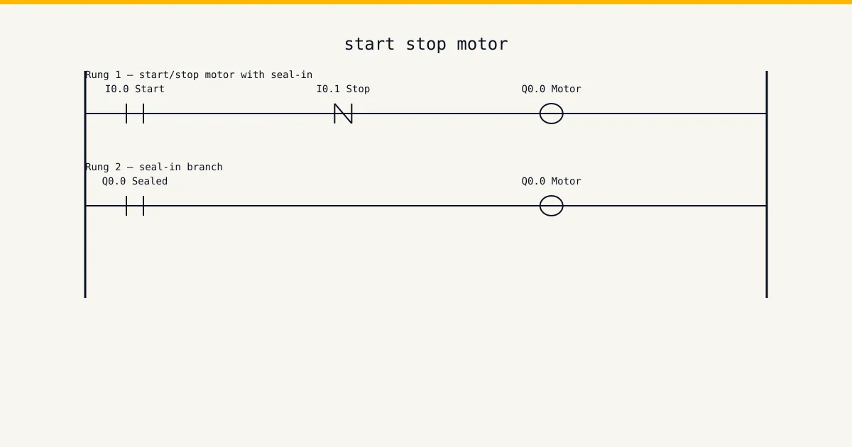
Contacts and coils are the first two ladder symbols every PLC engineer learns and the last two they stop misusing. The IEC 61131-3 standard defines four basic forms: the normally-open contact, the normally-closed contact, the output coil, and the negated output coil. Each vendor renders them slightly differently and treats edge cases differently — most painfully around dual coils on the same tag.
Try the simulator →What this instruction does
The bit logic family is one of the building blocks every working PLC engineer uses on a weekly basis. This page is the one-page reference: what the instruction is for, how the IEC 61131-3 standard form reads, where each major vendor's IDE diverges from the standard, and the mistakes that typically cost a shift on commissioning. We program these on real hardware ourselves; the worked examples below are the patterns that actually ship, not toy snippets. Read the page front to back the first time, then bookmark it as a quick lookup once the patterns are in muscle memory. The simulator covers each example in the sandbox at the free tier, so you can copy a rung from this page and run it without installing anything.
IEC 61131-3 syntax
The standard form is the place to anchor; once the IEC syntax is clear the vendor variations are easier to read. The block below is the canonical bit logic declaration as the standard defines it.
// Normally-open contact:    ─] [─
// Normally-closed contact:  ─]/[─
// Output coil:              ─( )─
// Negated output coil:      ─(/)─
A few notes on reading the syntax. The instance name on the left is what the runtime allocates state against — every call to a function block needs its own instance, never reused across rungs. The inputs after the colon-equals are how you bind real signals or constants to the block's parameters at call time. The dotted accessors after the call are how you read the output state on the next scan; the runtime only refreshes them at the call site, so referencing a dotted output from a rung that runs before the call gives you stale data.
Vendor implementations
Every major vendor implements the IEC standard form, but each adds its own conventions on top — IDE menu paths, datatype names, retentive variants. The mappings below are the ones that bite on a real commissioning visit. If your vendor is not listed here, the IEC form above is still the safe starting point; check the vendor docs for the brand-specific diff before you ship.
Siemens
TIA Portal LAD: drag from Instructions > Bit logic operations. Symbols labelled --| |--, --|/|--, --( )--.
TIA Portal warns on dual-coil usage at compile but does not block it. The last rung that writes the coil wins each scan; this is a frequent source of phantom outputs.
Allen-Bradley
Studio 5000: XIC (eXamine If Closed), XIO (eXamine If Open), OTE (OuTput Energise), OTL/OTU for latch/unlatch.
OTE is non-retentive — it drops on power loss or when its rung goes false. OTL/OTU are retentive and survive scan-to-scan; mixing OTE and OTL on the same tag breaks the program.
Schneider
EcoStruxure Control Expert LAD: same IEC symbols, also offers --(P)-- positive transition and --(N)-- negative transition coils.
Control Expert flags dual-coil with an animation table warning rather than a compile error. Use SET and RESET coils instead of two OTE-equivalents on the same tag.
Worked examples
The examples below are patterns we ship. Each one names the production context, the rung shape, and the parameter values that work in practice. Copy them into the simulator's sandbox to see the timing behaviour live before you put them on hardware.
Three-wire motor seal-in
Start pushbutton in parallel with the run-coil contact, both feeding the run coil through a normally-closed stop. Standard self-holding circuit, every plant uses it.
// Pseudo-ladder
// (StartPB OR RunCoil) AND (NOT StopPB) AND (NOT OL_Trip) -> RunCoil
Interlocked valve pair
Open and close commands wired with normally-closed contacts of the opposite valve to prevent simultaneous activation. The interlock is in the logic, not the wiring.
Common mistakes
The mistakes below cost real time on real projects. The first three appear on every commissioning visit; the rest are the second-tier traps that surface only under load or after a cold start. Run a paired-review pass against the list before you commit any rung that uses this instruction.
- Two OTE rungs writing the same tag — only the last rung in scan order wins, the first one is silently overridden every cycle.
- Treating OTL/OTU like OTE — the latch survives a CPU stop and restart, which surprises operators expecting a clean start state.
- Using a normally-closed input contact wired to a fail-safe sensor without testing the broken-wire case — the input reads false either way.
A pattern across all of these: the instruction itself is rarely the bug — the bug is in how the surrounding rung reads or writes the instruction's state. Check the rung shape first. The simulator's live trace pane shows .Q and .ET (or the instruction's equivalent state fields) on every scan, which is the fastest way to see whether the instruction is doing what you think it is.
How to practise this in the simulator
The simulator has a sandbox that lets you write a one-rung program using this instruction in under sixty seconds. Free tier covers it — open the simulator, drop the instruction onto a rung, wire two test inputs, and watch the .Q and .ET fields update in the live trace pane. The patterns above are exactly the patterns the curriculum builds on; this page is the one-page reference, the curriculum is the deliberate-practice version. Working through the curriculum's matching module gives you ten to fifteen variations on the same instruction shape, with feedback on each, and a portfolio piece at the end. The free tier is enough to verify the instruction works as documented; the Basic tier (USD 12 per month) unlocks the curriculum modules.
Start the free tier →Vendor reference
IEC 61131-3 standard is the canonical reference for the IEC 61131-3 standard form. For brand-specific quirks, Siemens Industry Online Support and Rockwell Automation Support are the canonical sources. When the standard and the vendor docs disagree, the vendor docs win for that vendor's hardware — the IEC form is the portable shape, the vendor form is what the firmware actually executes. For platform-pick decisions and longer brand context, see the Siemens and Allen-Bradley brand hubs.
What we don't claim
This site is not SAQA-registered, not MerSETA-accredited, and not an NQF-registered qualification provider. Our completion certificates are course-level only — they describe what you covered, not an NQF Level X qualification. The CCST cert from ISA is the portable industry credential we recommend; we are not an ISA cert delivery partner either, but our cert packs are CCST-aligned. The instruction reference on this page is a one-page summary of the IEC 61131-3 standard form plus vendor-specific quirks; vendor docs remain the canonical source for any production project.
Where this fits in a working week
A technician who has the bit logic family in muscle memory typically spends less than two minutes per rung writing one. The ones that take longer are the ones where the surrounding state machine has not been thought through; the instruction is fine, the design around it is what eats the day. The simulator's value is letting you exercise the design without paying for hardware time — write the rung, run it, watch the trace, fix the design, repeat. Twenty minutes in the sandbox saves a half-day of commissioning rework. The curriculum's matching module on the bit logic family takes about three to four hours of focused practice end to end and gives you the muscle memory plus the portfolio piece you can hand a hiring engineer. Petrochem, mining, FMCG, automotive, and water-utility sectors all use this family on a weekly basis; the patterns on this page are the same patterns the OEM engineering houses ship.
Load-shedding has changed the rung shapes that ship in SA. Power-recovery patterns — controlled shutdown on UPS hold, state recovery from retentive memory, sequenced restart of motor groups — sit on top of the bit logic family; understanding the instruction in isolation is step one, understanding how it behaves on a cold start after a 2.5-hour cut is step two. The simulator's restart-from-cut mode lets you exercise this without bricking real hardware. For institutional buyers — TVET colleges, private training providers, in-house engineering training departments — the bulk-licence option is the Teams tier, USD 199 per seat per year, minimum 5 seats. The training-centres page has the institutional pitch and the contact form.