for · South Africa
PLC Training for Instrumentation Technicians
PLC training for instrumentation technicians: your 4–20 mA and calibration discipline transfer straight in. The gap is discrete logic. Here's the bridge.
06 / visual field notes
Visual guide
6 original technical diagrams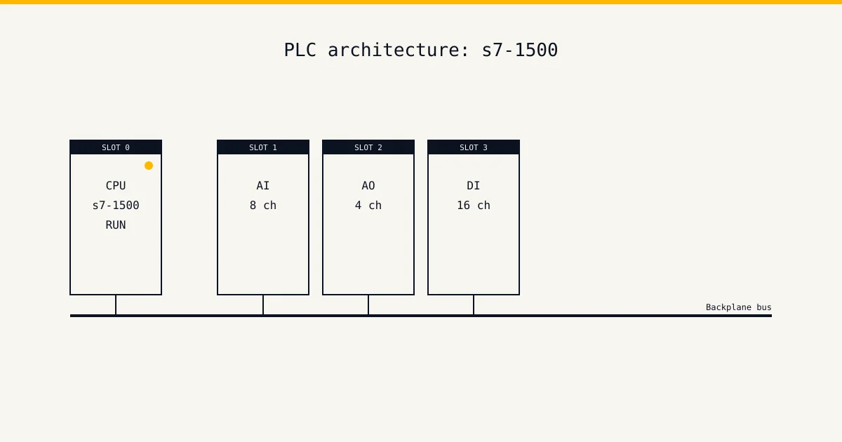
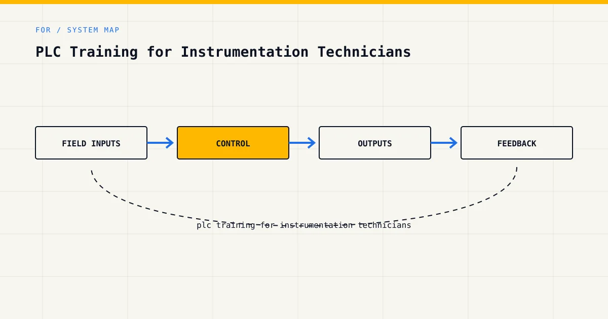
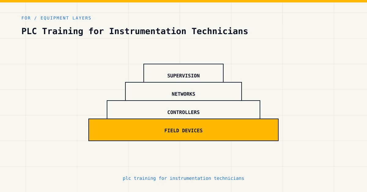
You spend your working life in the space between the transmitter and the marshalling cabinet. You can bench-check a DP transmitter, trim a loop, read 12 mA and know without doing the sum that you're sitting at half range. And then the loop disappears into the analog input card, the value turns into a number inside the program, and from that point on you're trusting someone else's scaling, someone else's alarm setpoints, someone else's interlock. For an instrument technician, PLC training isn't a career change — it's following your own signal one cabinet further. This page covers what your trade hands you for free, the one real gap, and a path that starts on your home turf instead of someone else's.
If you are still choosing between a short course, artisan route, college programme and engineering pathway, start with the broader instrumentation courses in South Africa guide. This page assumes the instrumentation foundation is already in place and focuses on the PLC bridge.
Try the simulator free →What you already know that transfers
The 4–20 mA loop, completely. Live zero, loop-powered versus four-wire, what an open circuit reads, why a value frozen at exactly 0% smells different from one frozen at -25%. When the curriculum reaches analog input handling, you'll be the person in the room for whom it's revision. Where everyone else has to learn what the transmitter is doing before they can learn what the program does with it, you start at the second step. Raw counts, engineering units, and the scaling between them are the program-side mirror of range and span: concepts you've carried since your first calibration.
Calibration discipline is testing discipline. Your trade taught you to verify in a fixed sequence: as-found, adjust, as-left, document. That's precisely the temperament that good PLC testing needs and that most beginners lack. When an exercise asks whether your alarm trips at the right level, your instinct will be to inject five points across the range and check each one, because that's how you'd check a switch on the bench. The grader rewards exactly that thoroughness. Programmers learn to test like instrument techs; you arrive already testing like one.
Loop drawings and signal paths. You read loop sheets, you follow a signal from sensing element through isolators and barriers to the card, and you know which junction box the fault is probably in. Tracing a value through a program (input channel, scaling block, comparison, interlock, output) is the same skill with the cabinet replaced by a screen.
Process behaviour. You know what a level does when the inlet valve opens, how fast a thermocouple responds versus an RTD, why a flow signal is noisy and a temperature isn't. That process feel is what separates someone who can write an alarm rung from someone who can choose a sensible deadband. It can't be taught quickly. You have it.
What's missing
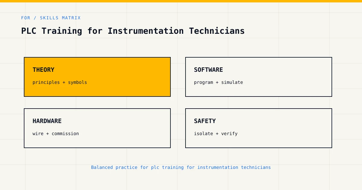
One honest gap, and it's the inverse of everyone else's: you live in continuous signals, and PLC logic is mostly discrete. Electricians arrive knowing contactors and lacking analog; you arrive knowing analog and lacking the binary world — interlocks, latches, sequences, states. A trim is a continuous adjustment; a seal-in rung either holds or it doesn't. The instrument tech's habit of thinking in ranges and drift has to grow a second mode: thinking in conditions and states. Which permissives are true right now? What latched, and what resets it? When six things tripped, which tripped first?
Concretely, that means three things to learn deliberately. Discrete logic itself: contacts, coils, and the latching patterns that hold a state after the condition that caused it has gone. Interlock thinking: the permissive chains that decide whether the pump you maintain is ever allowed to start, which is logic your loop sheets reference but never show. And sequences: steps and transitions, the batch and changeover logic where the program isn't holding a value steady but marching a process through states. None of this is harder than what you already do. It's just a different shape of thinking, and it needs the same deliberate practice your analog skills once did.
There's also the software workflow (projects, downloads, online monitoring), which is new to every trade and unremarkable. A few weeks of contact makes it routine.
The path
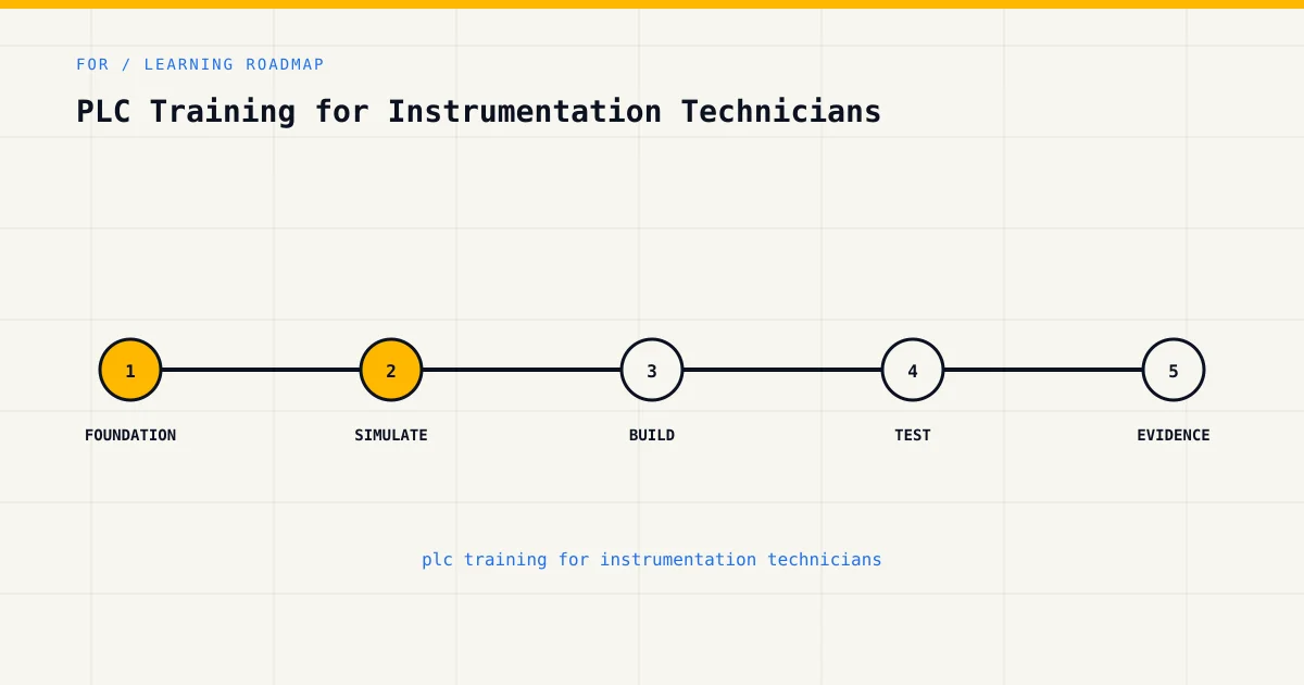
Built backwards from your strengths: start where you're at home, then cross the bridge into discrete logic.
- Analog signal types — start here precisely because it's revision. You'll learn the simulator's workflow on material you already command, which is the lowest-friction first session anyone can have.
- Scaling and resolution — the program-side half of your range-and-span knowledge: raw counts to engineering units, what 12-bit versus 16-bit resolution does to your 0.1% calibration pride, where rounding hides. The lesson most likely to be immediately useful at work this month.
- Tank level control — your first graded exercise, on a process you've instrumented: level transmitter in, pump control out, alarm limits. The grader checks behaviour across the whole range, not just at the setpoint — which is how you'd check it anyway.
- Water pump with float switches — the bridge exercise, and the most important step on this list. The same tank, but now the level arrives as two discrete floats instead of one continuous signal, and suddenly you need a latch: pump on at low, off at high, holding state in between. This is continuous-world you meeting discrete-world logic on familiar ground. When this exercise feels natural, the gap is mostly closed.
- Ladder logic basics and latching — the formal foundations under what you just did by instinct, with the contacts and coils reference bookmarked for the long haul.
- Pump alternation — duty-standby with changeover, pure state logic on equipment from your world.
- First-fault annunciator — alarm logic done properly: capturing which of several trips came first. As the person who maintains the trip initiators, you already know why this matters on an investigation; now build the logic that answers it.
After the path, comparison instructions is the reference page you'll lean on most — alarm and threshold logic is comparison work, and it's where analog and discrete meet for a living.
The SA qualification context
The instrument mechanician trade is the formal home of your skills in SA, and it's one of the few trades whose test brushes against control systems at all — but brushing is the right word, and the working PLC fluency a petrochem or mining instrument shop actually wants from its techs isn't in the syllabus. There's no registered stand-alone PLC qualification on the NQF for anyone, instrument trades included; the full picture of what certificates mean and don't mean in this country is at PLC certification in South Africa.
In practice the C&I techs who can work both sides of the marshalling cabinet are the ones the petrochem belt fights over. Instrument shops on the big sites run lean, the work is increasingly "the transmitter is fine, the problem is in the logic", and a tech who hands back "calibrated, no fault found" on a loop that's misbehaving in software hasn't finished the job — through no fault of their own, if nobody ever taught them the software half. That's the gap this path closes. If you're weighing the bigger move from instrument tech toward a controls technician role, the salary numbers are at PLC technician salaries in SA and the hiring mechanics at how to get hired as a PLC technician — instrument mechanicians make that move with the strongest analog foundation of any trade, and it shows in where they land.
For the vendor-neutral credential conversation your shop will eventually have, the relevant body is the ISA, whose CCST ladder is the cross-vendor benchmark for control systems technicians — worth knowing about even if you never sit it.
What it costs
The free tier (unlimited sandbox plus the first six lessons) carries you into the path above. Basic at $12 a month (roughly R220) opens the full curriculum and the wiring track. Pro at $29 is the tier built for your trade: it adds sensor school, a library of twenty-two industrial sensors with wiring diagrams and fault scenarios, plus the cert packs and portfolio export. For an instrument tech, Pro is the honest recommendation rather than the upsell. Full breakdown on the pricing page; how that stacks against classroom course fees is at PLC course prices in South Africa.
Common questions
Does the simulator model analog signals properly, or is it all switches and lamps?
Properly. Analog inputs carry realistic raw-count behaviour, the scaling work is real (counts to engineering units, resolution effects included), and exercises like tank level control grade your handling of a continuous signal across its range. You won't be trimming a HART transmitter in a browser — physical calibration stays physical — but the program side of every loop you've ever wired is here, behaving the way the card in your marshalling cabinet behaves.
Is PLC work part of the instrument mechanician trade test?
Only at the edges. The trade test examines instrument and control fundamentals, but writing and fault-finding PLC logic to the depth a working site demands isn't examined, which is exactly why instrument shops treat PLC fluency as a separately-acquired skill — and why techs who have it stand out. Nothing on this site changes your trade-test status either way; it builds the adjacent skill.
My shop is all Foundation Fieldbus and DCS. Does PLC logic still apply?
More than you'd expect. Function blocks, scaling, alarm limits and interlock logic are shared DNA across PLCs and DCS platforms — the IEC 61131-3 languages underpin both worlds, and ladder-and-logic fluency reads across to DCS configuration far more directly than the vendors' marketing departments would like you to believe. Learn the patterns here, and the platform politics matter less.
How long before this is useful at work?
Faster than for any other trade, because your first three steps are revision plus workflow. Most instrument techs report the scaling lesson paying for itself within the month — usually the first time a "transmitter fault" turns out to be a scaling block configured for the old range, found by the tech who could finally read it.
Start with the free tier →What we don't claim
We are not SAQA-registered, not MerSETA-accredited, and not an NQF-registered qualification provider. Nothing here is a trade-test substitute, an instrument mechanician qualification, or a credential with national standing — our completion records describe practice done, nothing more. The simulator also doesn't replace bench work: calibration stays a physical skill, and we'd be suspicious of anyone telling you otherwise. What this platform does is teach the program side of the loops you already maintain, with graded exercises and honest scoring. The career observations above are patterns from working techs, not guaranteed outcomes.