reference · South Africa
IEC Bit Shift Instructions: SHL, SHR, ROL and ROR
IEC bit shift instructions explained with byte examples, signed right shifts, status masks and conveyor tracking rules for South African PLC learners.
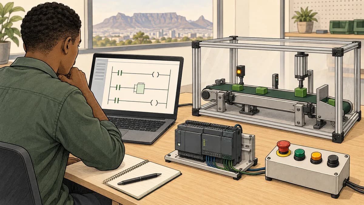
IEC bit shift instructions move bits within a value; rotate instructions move them around a fixed-width boundary. SHL, SHR, ROL and ROR are useful terms to recognise, but the result depends on operand width, type and the selected platform. Before predicting an output, write down exactly which bits exist and what should happen to a bit that leaves either end.
For PLC learners in South Africa, useful applications include interpreting packed status data and understanding a simplified tracking register. These are different tasks. A calculation on one byte is not automatically equivalent to a vendor's stateful array-shift instruction, and neither establishes that a physical conveyor has moved the required distance.
This site has a commercial connection to PLC Simulator. The linked educational tools support learning and testing; they do not guarantee support for arbitrary native shift instructions or validate a real reject mechanism. The illustrations are conceptual learning scenes, not screenshots of vendor software or production results.
Shift left, shift right, rotate left and rotate right
For the first example, define an eight-bit unsigned value. Number its bits from zero at the rightmost, least-significant position through seven at the leftmost position. A logical shift fills newly vacated positions with zero. A rotation returns the departing bit at the opposite end of the same eight-bit value.
| Operation | Direction in this bit display | What happens at the vacated end? |
|---|---|---|
| Logical shift left by one | Towards the higher bit numbers | Zero enters bit zero |
| Logical shift right by one | Towards the lower bit numbers | Zero enters bit seven |
| Rotate left by one | Towards the higher bit numbers | The old bit seven enters bit zero |
| Rotate right by one | Towards the lower bit numbers | The old bit zero enters bit seven |
The word “logical” matters in that table. An arithmetic right shift can extend the sign bit instead. Do not turn an unsigned teaching example into a blanket rule for every signed input accepted by every PLC instruction.
A rotate preserves the number of set bits within the stated width. A logical shift can discard set bits. If a tracking requirement says that a departed item must leave the model, wrapping its marker to the entrance would represent a different process.
Worked byte example: predict the result before running it
Use the input 10110001 in binary, B1 in hexadecimal, or 177 as an unsigned decimal number. All three representations describe the same eight bits. Apply each operation independently to that original input, rather than applying the rows cumulatively.
| Operation on the original byte | Expected binary result | Hexadecimal | Unsigned decimal |
|---|---|---|---|
| Logical shift left by one | 01100010 | 62 | 98 |
| Logical shift right by one | 01011000 | 58 | 88 |
| Rotate left by one | 01100011 | 63 | 99 |
| Rotate right by one | 11011000 | D8 | 216 |
The left shift discards the original most-significant one. The left rotate puts that one into the least-significant position, explaining the difference between 62 and 63 hexadecimal. At the other end, the right rotate preserves the original least-significant one by moving it to bit seven.
Draw eight boxes if the hexadecimal notation is distracting. Label their weights 128, 64, 32, 16, 8, 4, 2 and 1 from left to right. Move the marks according to the chosen rule, then calculate the displayed decimal value. This gives you an expectation independent from the program you are checking.
Do not infer execution time from this table. It establishes mathematical results under explicitly stated rules. A native project needs the correct instruction, input type and count, followed by observation in the chosen controller or supported simulator.

Operand width can change the answer
Keep the numerical input 177, but now represent it as the sixteen-bit pattern 0000000010110001. A rotate right by one produces 1000000001011000, which is 8058 hexadecimal. The eight-bit rotate produced D8. Both are correct for their respective widths because the departing bit returns at a different boundary.
This is why declaring a wider destination is not a reliable way to request a wider operation. Establish the type used for the input and operation itself. A conversion performed after a narrow operation cannot recover bits that the narrow operation already discarded.
The CODESYS SHL documentation explicitly identifies the input data type as determining the width. It also describes target-dependent behaviour when the count exceeds that width. Validate counts deliberately instead of relying on an accidental zero or modulo result.
The CODESYS ROR reference likewise explains that input width controls rotation and that output-variable type does not change it. It notes type inference for constants. When writing a reproducible lesson, use explicitly typed operands so another learner can understand which width you intended.
Signed right shift is not always logical right shift
A bit pattern and its signed numerical interpretation are related but different concepts. In an eight-bit two's-complement teaching model, 11111101 represents negative three. A logical right shift by one produces 01111110, which is 126. A sign-extending arithmetic right shift produces 11111110, representing negative two.
These are not interchangeable calculations. Integer division of negative three by two also requires a specified rounding rule. Truncation towards zero gives negative one, while rounding down gives negative two. Avoid substituting division or a cast for a shift without checking the target's documented semantics and the required result.
For the documented STEP 7 V21 SCL instruction, Siemens describes zero filling for unsigned values and sign-bit filling for signed values in its SHR reference for S7-1200, S7-1500 and S7-1200 G2. Therefore, “Siemens SHR always inserts zero” is not a sound general rule.
Keep data transport and numeric calculation separate. If a field is a packed status word, treat it according to its documented bit layout. If it is a signed measurement, use a calculation whose numeric behaviour matches the requirement. A familiar hexadecimal pattern is not enough to decide which operation is appropriate.
Counts, zero shifts and boundary cases
A test plan should include a count of zero, a count of one and a count near the operand width. Also establish how the application handles a negative or excessive count before passing it to an instruction. The permitted count type and out-of-range behaviour are part of the platform contract.
For the mathematical examples here, counts are deliberately limited to zero through seven for eight-bit operations. A zero count leaves the original value unchanged. No result in the worked table relies on behaviour for an excessive count, and the examples do not prescribe a universal rule for such counts.
If an HMI or communications value supplies the count, validate it as an input. Do not let a type conversion silently turn an invalid request into a different valid count. Report the rejected request separately from the last successful result so a consumer does not mistake retained data for a new calculation.
Our array and index reference covers the related discipline of checking a calculated access before using it. Shift counts and array indices are different operands, but both benefit from an explicit range and a defined failure result.

Pack and inspect a status byte
Suppose a fictional interface assigns bit zero to Ready, bit one to Running, bit two to Fault and bit three to Manual. Bits four through seven are reserved and are transmitted as zero. This is a teaching layout, not a vendor protocol or a universal SCADA convention.
If Ready, Fault and Manual are true while Running is false, the packed byte is 00001101, or 0D hexadecimal, which is 13 decimal. Its value is 1 plus 4 plus 8. The receiver must use the same documented bit numbering and meaning to interpret it correctly.
| Bit position | Meaning in this exercise | State in 0D hexadecimal |
|---|---|---|
| 0 | Ready | True |
| 1 | Running | False |
| 2 | Fault | True |
| 3 | Manual | True |
| 4–7 | Reserved | Zero |
To inspect the Fault field mathematically, shift the unsigned byte right by two and mask with one. For 13, the shifted value is 3 and the masked result is 1. Masking matters because shifting alone leaves the other higher-order fields in the result.
To set Running without changing the other fields, combine the original byte with mask 02 hexadecimal using bitwise OR. The result is 0F. To clear Fault from the original byte, combine it with the eight-bit mask FB hexadecimal using bitwise AND; the result is 09. These are independent operations on the original 0D fixture.
Document the width of the mask. A language's unrestricted integer complement or a wider signed temporary is not automatically the eight-bit mask you intended. In a native implementation, verify the selected bitwise operators and conversions. Keep permission to change a process state separate from the ability to manipulate its reported status bits.
A shifted word is not a complete message format
Packing four flags into one byte says nothing about multi-byte ordering, message length, freshness or acknowledgement. If the interface later expands to a sixteen-bit word, specify which byte is sent first and how the receiver reconstructs it. Rotating a word is not a general correction for reversed bytes.
Also define whether the flags represent a single coherent observation. A receiver should not have to guess whether Ready came from one update and Fault from another. The actual data exchange may provide a suitable consistency mechanism, but the bit layout alone does not establish one.
Version the layout when meanings change. Reusing a formerly reserved bit for a new meaning can require a receiver update even though the packet remains the same size. A useful interface record includes the bit map, reserved-bit rule, validity or age information and at least one known example such as 0D.
Our PLC communications troubleshooting guide helps separate data interpretation from transport and connection problems. A message can arrive successfully while being decoded with the wrong field definition.

Conveyor tracking needs a movement event
A tracking register can model positions only if its update event has a defined relationship to movement. Shifting on every PLC scan makes the marker advance according to program execution, which is not necessarily proportional to conveyor travel. A stopped belt can still have a running PLC program.
A product-detection pulse also does not automatically represent one fixed distance of travel. Products may have gaps, different spacing or missing detections. Choose the position model and movement measurement appropriate to the actual application. Encoder-based tracking introduces its own resolution, direction and missed-pulse considerations.
For a paper exercise, explicitly define an accepted movement event as one slot advance. Insert a new Boolean marker at the entrance and remove the oldest marker at the exit. This is sufficient to test register logic without claiming a physical reject position or actuator timing.
The sorting-by-height exercise gives broader context for deciding what a simulated item classification means. A classification result and a later position estimate are separate pieces of information that need to remain associated with the same item.
Worked four-slot tracker
Use four bits, with bit zero representing the newest slot and bit three the oldest. On each accepted movement event, first record the old bit three as the departing marker. Then shift the remaining bits towards higher positions, discard the departed bit and insert the incoming marker at bit zero.
Start with 0000. Supply incoming markers 1, 0, 1, 0, 0, 0 and 0. Every row represents one accepted movement event, not one arbitrary program scan. The state shown is after the update, while the departing marker comes from the state before that update.
| Movement event | Incoming marker | State after update | Departing marker |
|---|---|---|---|
| 1 | 1 | 0001 | 0 |
| 2 | 0 | 0010 | 0 |
| 3 | 1 | 0101 | 0 |
| 4 | 0 | 1010 | 0 |
| 5 | 0 | 0100 | 1 |
| 6 | 0 | 1000 | 0 |
| 7 | 0 | 0000 | 1 |
The marker inserted at event 1 leaves at event 5, after four subsequent accepted advances. The marker inserted at event 3 leaves at event 7. This timing follows the stated insertion and observation convention. Reading a different bit before rather than after the shift can change the apparent delay, so record that convention with the test.
If no movement event is accepted, the model holds its register unchanged. A real design must additionally decide what a held or previous departing indication means to its consumer. This exercise reports departure only as a result of an accepted update; it does not drive a solenoid or define a safe machine action.

BSL and BSR are not aliases for every SHL or SHR
Rockwell's Logix Designer BSL documentation describes an operation on a DINT array with a CONTROL structure, a source bit and a length measured in bits. Its unload field records the bit shifted out. This is a different interface from a pure word operation that returns a shifted value.
The same documentation identifies a major fault of type 4, code 20 when the length exceeds the array size. It does not support the claim that every such mistake silently corrupts whichever unrelated tag happens to be next. Use the actual instruction's diagnostics and memory requirements when reviewing the project.
Check its execution table and control behaviour when connecting a movement signal. Do not assume that holding a rung true or invoking a block repeatedly produces the exact event sequence in the paper model. Establish the required trigger and rearming behaviour in the native training environment, and observe both the register and control fields.
Allocate the required storage and document which range belongs to the tracking operation. Bits beyond a configured tracking range should not be treated as independently preserved application data without instruction-specific evidence. Reusing a control structure or overlapping storage between unrelated operations can also undermine the intended state ownership.
Stops, restarts and lost synchronisation
Stopping movement should not make a position model continue advancing merely because the controller still executes. However, retaining a register through a restart is not enough to prove it still matches the items on the conveyor. Items may have been removed, moved manually or left in an uncertain position.
Define what makes tracking valid and what invalidates it. Possible exercise events include an unexpected direction change, a missing movement update or a deliberate reset. An application needs an explicit recovery policy; silently clearing all bits can also conceal items that remain physically present.
In a South African training setting, a power-interruption scenario should distinguish software state from verified physical position. Ask which aspects the simulator actually models and which require equipment observation. Do not present a saved register or a browser restart as proof that a real line will resume synchronised operation.
For a lesson, mark tracking invalid after a deliberately lost event and require a documented reset of the fictional model. That teaches the significance of lost information without inventing a universal production recovery procedure.
Tests that distinguish the common mistakes
For word operations, test all-zero and all-one values, a single bit at each boundary and a mixed pattern such as B1. Include typed eight-bit and sixteen-bit inputs with the same numerical value. Compare the expected bit pattern as well as the displayed decimal value.
For packing, test each flag individually and then combinations. Verify that setting or clearing one field preserves the others and follows the reserved-bit rule. Decode the packed result using an independently written expectation rather than copying the exact same mistaken bit map into both sides of a test.
For tracking, use separated markers, consecutive markers, an empty advance and a pause with no accepted movement. Check the departing marker before modifying the stored register. Add a deliberately lost event and confirm that the exercise's validity policy becomes visible rather than quietly declaring the tracker correct.
PLC program testing exercises can support the habit of predicting and comparing results. The numerical checks for this guide validate its stated bit models, not native instruction timing, electrical behaviour or machinery safety.
Questions learners ask about shift instructions
Is shifting left the same as multiplying by two?
For an unsigned fixed-width value, a one-bit left shift resembles multiplication by two only while considering how overflow is handled. Bits beyond the defined width can be discarded. A numeric calculation and a bit manipulation must use the same explicitly stated range and overflow rules before you treat them as equivalent.
Why does ROR give a different result after I change BYTE to WORD?
The rotation boundary has changed from eight bits to sixteen. A departing low bit returns at bit fifteen in the wider operation. Check the input type, not only the destination display or the numerical value written in the source.
Can I use rotate for conveyor rejects?
Only if recirculating the marker is actually part of the model. Ordinary departure tracking removes an item from the represented range. Rotating it back to the entrance can create a false future departure.
Does one photoeye pulse equal one tracking position?
That depends on the physical measurement and model. A detection event is not automatically a fixed movement increment. Define the relationship and validate it on the relevant equipment before using it to time an action.
What should a PLC course assess here?
A learner should predict typed shift results, explain logical versus signed right shift, decode a documented status byte and trace a small movement-driven register. Ask for hands-on access to the actual software if native BSL or BSR diagnostics are part of the course promise.

Keep the bit model and the application connected
Save the operand width, bit numbering, accepted count range and expected results with the exercise. For tracking, also record the movement event, insertion position, departure observation and invalidation rule. Those details make a small example reproducible instead of relying on a familiar instruction name.
The Structured Text learning tools can support earlier work on readable expressions and test cases. Continue in the required vendor environment when the learning objective is its native instruction behaviour, and label exactly what your evidence demonstrates.