brands · South Africa
ISPSoft Ladder Basics: DVP Addresses, Logic and Testing
Learn ISPSoft ladder basics for Delta DVP: octal addresses, input polarity, seal-in logic, stop priority, COMMGR context and defined simulation tests.
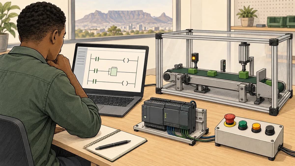
ISPSoft ladder learning for a Delta DVP PLC should start with the exact target, the meaning of each input and a testable requirement. Learn to distinguish device addresses, programme state, communication setup and actual hardware behaviour. A rung that looks familiar can still be wrong because a stop input has the opposite meaning from the one the author assumed.
This guide develops a fictional seal-in exercise, explains DVP address notation and outlines the checks around a native ISPSoft practical. It deliberately separates a paper or simulated result from execution on a real controller. Use the current instructions for your installed software and controller when moving beyond the educational exercise.
Confirm the target and engineering environment
Record the complete DVP model, software version and project origin before creating or opening a practical. The DVP platform guide explains why controller variants differ in I/O, communication and supported functions. Do not assume an exercise for one model describes every DVP target.
Delta's ISPSoft product page provides the vendor route for software information. Check the applicable download and installation requirements. The broader Delta training guide also explains why WPLSoft and ISPSoft should not be treated as completely separate choices for unrelated controller families.
A classroom project should identify whether it runs in a simulator or on an isolated training PLC. It should also identify the programme organisation and execution arrangement supplied by the instructor. A POU existing in a project tree is not, by itself, a useful demonstration that its logic is executing as intended.
Keep the native setup reproducible
Use the course's documented target selection and a small named project. Retain the supplied initial state and exercise specification. If the project comes from another learner or workstation, confirm its identity before interpreting observations or changing it.
Avoid relying on guessed shortcut keys or default programme names. These details can vary with versions and setup. Ask the instructor to show where the programme is assigned and how to confirm that the intended logic runs. Understanding that relationship is more valuable than memorising an unsupported menu sequence.
Read X, Y, M and D as different device categories
For the DVP context, X identifies input devices and Y output devices. M is used for auxiliary bit devices, while D identifies data registers. Timers, counters and special devices have their own documented functions and ranges. Consult the specific controller manual rather than applying one universal range to every model.
DVP X and Y numbering uses octal notation in the applicable device tables. The sequence goes 0 through 7, then 10 through 17. Beijer's Delta DVP driver documentation explicitly identifies X and Y as octal-addressed devices in its driver context. Its address ranges should not be mistaken for the physical channel count of every CPU.
Consequently, the octal suffix 10 represents decimal index 8, not 16. The suffix 20 represents decimal index 16. A valid device label still needs to correspond to a supported device or channel in the actual configuration. Correct number conversion does not establish that hardware exists at that address.
| Octal X/Y suffix | Decimal index | What the conversion establishes |
|---|---|---|
| 7 | 7 | Last digit before the octal rollover |
| 10 | 8 | First index after 7 |
| 17 | 15 | Last index in the next group |
| 20 | 16 | Beginning of the following group |
Do not invent X8 or Y9 within an octal device sequence. Also do not apply octal conversion indiscriminately to every number in the project. Device categories, constants and external client addressing conventions must be interpreted according to their documentation.

Use symbols to make the exercise meaning visible
For the fictional lesson, use descriptive names such as StartRequest, StopRequest and RunMemory. If the instructor maps them to actual device addresses in a native project, keep a table linking name, address, type and meaning. The names in this article are educational signals and are not a wiring specification.
A StopRequest that is true when the learner asks to stop differs from a HealthyStopLoop that is true when a physical input circuit is healthy. They may be related through an adapter or interpretation rule, but substituting one for the other without changing the logic can invert the result.
The contacts and coils guide explains why a PLC contact symbol tests a Boolean condition. A normally closed-looking instruction does not, by itself, tell you how a physical pushbutton is wired. Separate electrical contact arrangement from the programme's interpretation of the input bit.
For this lesson, both request inputs must be explicit Boolean values. Missing or malformed input data is outside the two-state model. If the course extends the exercise to data validation, define that behaviour separately rather than silently converting unknown values to false.
Define the seal-in requirement before drawing it
The fictional RunStudy has StartRequest and StopRequest inputs and a stored Boolean RunMemory. Initially RunMemory is false. At each study observation, StopRequest has priority: when it is true, the next RunMemory is false. Otherwise, StartRequest or the previous RunMemory can make the next RunMemory true.
Written as a Boolean state update, the rule is NextRun := (StartRequest OR PreviousRun) AND NOT StopRequest. This is a teaching expression for reasoning about one update. It is not a claim that the names are already declared in an ISPSoft project or a recommendation for a complete motor control or safety system.
A ladder representation has a parallel choice between StartRequest and the previous run state, followed in series by the condition that StopRequest is false, leading to the run-state result. The learner should explain each relationship before entering the network in a native editor.
The start-stop seal-in exercise provides a broader learning route. Keep the scope of each implementation clear. Real equipment requires additional design and protective measures that are not supplied by this three-variable classroom model.
Check all combinations of the state update
There are eight combinations of StartRequest, StopRequest and PreviousRun. Check them all for this small model. The simultaneous start and stop cases are especially useful because they expose whether stop priority was implemented as required.
| StartRequest | StopRequest | PreviousRun | NextRun |
|---|---|---|---|
| False | False | False | False |
| False | False | True | True |
| False | True | False | False |
| False | True | True | False |
| True | False | False | True |
| True | False | True | True |
| True | True | False | False |
| True | True | True | False |
The table describes the declared state update, not every aspect of controller execution. It does not establish initialisation after a particular restart, physical input filtering or the response of a connected output device. Those require separate requirements and checks.

Trace a complete sequence, including restart after stop
Start from false. Supply these seven input pairs in order: neither request; start only; neither request; both requests; neither request; start only; neither request. The expected RunMemory values are false, true, true, false, false, true and true.
The second observation starts the virtual state. The third shows seal-in after StartRequest is released. The fourth demonstrates stop priority. The fifth shows that clearing StopRequest alone does not restart the state when StartRequest is false. The sixth supplies a new start request.
| Observation | StartRequest | StopRequest | RunMemory after update |
|---|---|---|---|
| 1 | False | False | False |
| 2 | True | False | True |
| 3 | False | False | True |
| 4 | True | True | False |
| 5 | False | False | False |
| 6 | True | False | True |
| 7 | False | False | True |
Now hold StartRequest true while releasing StopRequest after the fourth observation. The declared rule becomes true again because a start request is still present. If the intended behaviour requires a fresh rising edge after stop, that is a different requirement and needs additional state. Do not claim the basic seal-in rule already implements that condition.
This distinction is useful in a course assessment. Ask the learner to predict the held-start case before running it, then explain whether the observed result matches the stated requirement. A surprising result is not automatically a software fault; it may expose an unstated expectation.
Diagnose two plausible ladder mistakes
The first mistake uses StopRequest directly as a required true condition instead of negating it. The virtual state then becomes enabled by the request intended to stop it. A normal start-only test exposes the contradiction: the required result is true, but the mistaken rule remains false.
The second mistake is StartRequest OR (PreviousRun AND NOT StopRequest). It allows StartRequest to bypass StopRequest. The simultaneous start-and-stop case exposes it immediately. If the learner only tests start, release and stop separately, this wrong grouping may appear acceptable.
These mistakes can be represented in ladder just as easily as in text. Correctness comes from the relationship to the requirement and the chosen evidence, not from the visual familiarity of a rung. Ask the learner to identify which branch or series relationship implements the priority.
The latching guide develops further distinctions between state, feedback and reset behaviour. When extending an introductory exercise, change one requirement at a time and add the case that could reveal an incorrect implementation of that change.

Separate compilation, communication and execution
A programme check can find certain structural or target-related errors. It cannot establish that the input meaning is correct or that the implemented priority matches a written requirement. Keep the truth table and sequence tests after the project builds successfully.
Communication setup is another separate step. Delta's ISPSoft V2.00 and COMMGR V1.00 RS-232 example configures and starts a driver in COMMGR, then selects it in ISPSoft communication settings. The version-specific example illustrates the relationship between the tools; it should not be presented as an exact universal workflow for every current release or interface.
For a native course practical, verify the selected driver, target identity and connection information before an authorised transfer. Read the prompts and controller documentation supplied for that environment. Do not assume every download automatically stops and restarts every DVP model in the same way.
A successful connection identifies a communication path; it does not prove that the correct exercise is running. Confirm the project and selected target, then observe the intended programme behaviour. Preserve the known initial state so the sequence can be repeated meaningfully.
Do not use physical forcing as the first lesson
Use the simulator's supported input controls or the isolated training setup specified by the instructor for the educational sequence. A generic instruction to force any X or Y device is not a reliable cross-model procedure, and a force is different from normal programme-driven behaviour.
If a course teaches forcing or temporary overrides, it should explain the exact supported mechanism, authorisation, affected devices and removal verification for that environment. The watchdog and force-discipline guide provides context for that separate topic. It should not be confused with the simple state model in this article.
Understand what the simulator can and cannot establish
Delta's WPLSoft and ISPSoft simulator FAQ explains that simulated results are not identical to actual PLC execution and that timing depends on the PC. It also lists unsupported specialised instructions in the context described. Check the current applicable manual for the target and software version used in your class.
The small Boolean model here does not rely on fieldbus, high-speed pulse output or measured physical timing. That makes it suitable for careful conceptual practice. It does not make a more complex project automatically valid in simulation or on hardware.
Record the result's origin. “Paper trace”, “educational browser simulation” and “ISPSoft simulator” are different descriptions. If the exercise is later executed on an isolated DVP training controller, add that environment and its observations separately rather than rewriting the earlier evidence as hardware validation.

Extend the lesson into timers, counters and data carefully
Before adding a timer, define the timing requirement and the timer behaviour you expect when its enabling condition changes. Confirm the relevant timer instruction and time base for the target. A bare timer address or constant copied from another example does not fully describe the intended delay.
Before adding a counter, define what constitutes one event. A true input held across several observations differs from several false-to-true transitions. The timers and counters guide provides a conceptual route, after which the native Delta instruction needs its own verification.
For data registers, state the representation, units and expected range. A wider value may occupy multiple registers under the applicable instruction and addressing rules. Do not assume a generic prefix or a register pair means the same thing in every editor or external driver.
The data conversion guide helps learners identify those boundaries. Test zero, a normal value, a boundary and an invalid case where the exercise defines one. A value that appears plausible on a screen can still have the wrong interpretation.
Build a troubleshooting record from the exercise
When the virtual state differs from the expected trace, record the observation number, inputs, previous state and result. Compare it with the declared rule before changing the programme. This tells you whether the issue concerns polarity, grouping, initial state or another assumption.
Make one correction and repeat the case that failed, then repeat the rest of the small sequence. A change can fix the simultaneous-request case while breaking ordinary seal-in. The full eight-case table is small enough to retain as a useful regression check for this model.
If the native programme does not appear to run, separate that question from the Boolean rule. Check the actual project organisation, target and execution arrangement with the instructor. The PLC troubleshooting guide supports that separation between environment evidence and logic evidence.
A useful learner report includes the requirement, target or model, address or symbol table, expected trace, observed trace and explanation of the correction. Screenshots can support the report, but they should not replace the information needed to reproduce the result.
What South African learners should ask of an ISPSoft course
Ask for the exact controller, software version and individual practical tasks. A course can use a small DVP effectively if its scope is clear. It should not imply that one introductory exercise covers every Delta family, communication feature or application type.
Request a sample assessment. Can the learner explain stop polarity, demonstrate the simultaneous-request case and identify a wrong address notation? Those concrete tasks are easier to judge than a broad promise of becoming an advanced programmer in a fixed number of days.
Compare the full course cost, including equipment and software access, assessment and continued practice. The South African PLC course price guide helps organise that comparison. Do not assume an attendance certificate represents a registered qualification or independent assessment unless the provider supplies the relevant evidence.
For institutions, the training-centre guide can help define a small evaluation lesson. Require individual prediction and explanation even when learners share equipment. A group producing one working rung does not show that everyone understood its state and priority.
Continue with a relevant educational practice route
This site is commercially connected to PLC Simulation Software. Its Delta DVP programming practice guide explains the educational address notation and supported subset available in the product. Check that scope before choosing an instruction or exercise.
Use its PLC programme testing resources to practise the relationship between a requirement and an informative test. This is preparation, not a claim that the product imports native ISPSoft projects, reproduces every DVP instruction or proves physical I/O behaviour.
Follow the educational work with the appropriate supervised native practical. Keep the distinction visible in your portfolio. A clear explanation of one corrected state-update mistake can be useful evidence of learning without being presented as complete commissioning experience.

Questions about ISPSoft ladder basics
What does Y10 mean in the DVP octal sequence?
Its suffix represents decimal index 8. The octal sequence moves from 7 to 10, and from 17 to 20. Check the actual controller's available devices and the external driver's mapping convention before associating that label with a physical or network address.
Is a normally closed ladder contact the same as a normally closed button?
No. The ladder instruction evaluates a Boolean condition. The physical circuit and the programme's interpretation determine what the input value means. Define whether the signal represents a stop request or a healthy circuit before choosing the condition.
Does the basic seal-in rule require a fresh start after every stop?
Only under the input sequence stated. If StartRequest remains true when StopRequest clears, the model shown here starts again. Requiring a new rising edge is an additional requirement that needs further state and testing.
Does successful compilation prove the rung is correct?
No. The wrong stop polarity or branch grouping can still be structurally valid. Check the result against the truth table and sequence, including simultaneous requests and the initial state.
Can a simulator prove a DVP project's hardware timing?
No. Delta documents differences between simulator and PLC execution. Use simulation for its supported learning scope and obtain target-specific evidence for hardware, communication and timing requirements.
What is a good first portfolio item?
A small declared requirement, symbol meanings, initial state, full test table and an explained correction. Name the environment used for the results. That gives an instructor or reviewer something concrete to assess and reproduce.