learn · South Africa
PLC Timers and Counters: Delay, Pulse and Reset Examples
Learn PLC timers and counters through timed traces, pulse and reset tests, retained-time examples and practical questions for South African PLC courses.
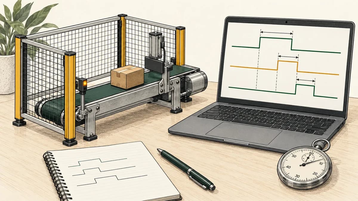
PLC timers and counters turn repeated program evaluations into useful decisions about elapsed time and observed events. A timer answers a timing question; a counter records defined changes in its input. Both require stored state, explicit reset behaviour and a clear understanding of when the instruction executes.
This tutorial compares on-delay, off-delay and pulse behaviour, then separates accumulated enabled time from an ordinary delay. It finishes with a small edge counter whose reset and upper limit are written into the specification. All timestamps and signals in the worked examples are supplied to a disconnected learning model.
For South African learners choosing PLC training, these examples provide a practical assessment: predict the result before running the program, explain the boundary cases and identify which details must be checked in the selected controller's documentation. The models do not command physical fans, valves or conveyors.
Start with the timing question, not the instruction name
Write the required behaviour in one sentence. “Become true after the input has remained true for two seconds” describes an on-delay. “Remain true for two seconds after an observed true input becomes false” describes an off-delay. “Produce a two-second pulse when a fresh event arrives” describes a pulse requirement, but still needs a rule for additional events during that pulse.
A fourth question is different: “Accumulate five seconds across separate enabled intervals.” That requires retained accumulated time. It should not be confused with a normal on-delay that starts afresh after its input becomes false.
| Learning requirement | State that must be considered |
|---|---|
| On-delay | When the current uninterrupted true interval began |
| Off-delay | Whether the input was previously true and when it fell |
| Pulse | Whether a pulse is active and which event started it |
| Accumulated time | Total enabled duration and the reset policy |
| Event counter | Previous input state, current count and limit policy |
The names TON, TOF and TP appear in the CODESYS Standard library references used below. RTO is a name used by particular vendor instructions; it is not a universal replacement for TP in every timer library. Similar labels do not establish identical operands, startup behaviour or memory retention.
Keep the PLC scan-cycle tutorial open while practising. A timer's state changes when its implementation evaluates time and input data. A screen refresh is not necessarily the same event as a program evaluation.
Define the shared assumptions for the worked traces
Use integer milliseconds that never move backwards. Each row is one evaluation. The preset remains fixed at 2,000 ms for the on-delay, off-delay and pulse examples. Inputs change only as described by the table; there is no claim about unobserved physical changes between rows.
Initialise each example separately. Do not carry a timer's internal state from one table into another. Elapsed time starts at zero on the first evaluation that begins an interval, and the displayed elapsed value is capped at the preset where it is shown.
An exact boundary belongs to the completed interval: an on-delay started at 100 ms is complete when evaluated at 2,100 ms. If no evaluation occurs at that instant, the output is first observed complete at a later evaluation. A timer does not make a program execute at a deadline merely because the deadline exists.
Keep the preset, elapsed value and output in separate columns. Avoid describing an elapsed number as an output, or assuming that a bit called Done has the same interpretation for every instruction family. State the Boolean behaviour you require.

TON: require one uninterrupted true interval
The on-delay model starts its interval when it first evaluates a true input after being reset. While the input remains true, elapsed time is the difference between the current supplied time and that start time. Q becomes true once that difference reaches 2,000 ms.
Any evaluation with the input false clears the interval, sets elapsed time to zero and sets Q false. The next true input begins a new interval; it does not recover the time from the previous attempt.
| Time ms | Input | Elapsed ms | Q |
|---|---|---|---|
| 0 | 0 | 0 | 0 |
| 100 | 1 | 0 | 0 |
| 2099 | 1 | 1999 | 0 |
| 2100 | 1 | 2000 | 1 |
| 2200 | 0 | 0 | 0 |
| 2300 | 1 | 0 | 0 |
The official CODESYS TON reference documents the input transitions, preset and elapsed-time output, with Q false when IN is false and true after the delay while IN remains true. Check those named parameters in the actual library used by your project.
A useful extension interrupts the first attempt at 1,500 ms. On the next true evaluation, expect zero elapsed time for the new attempt. If your result instead resumes from the interrupted value, investigate which instruction and reset path you actually implemented.
The on-delay motor-staging exercise applies timing to virtual sequence decisions. Use it after you can explain this smaller trace independently.
TOF: delay the return to false
The off-delay model begins with Q false and no active interval. A true input immediately makes Q true and clears any off-delay interval. When a previously true input is observed false, start the two-second off-delay while retaining Q true.
If the input stays false through the deadline, Q becomes false. If it returns true before that deadline, cancel the pending off-delay, reset its elapsed value and keep Q true. An input that has always been false does not generate a startup run-on in this model.
| Time ms | Input | Elapsed ms | Q |
|---|---|---|---|
| 0 | 0 | 0 | 0 |
| 100 | 1 | 0 | 1 |
| 600 | 0 | 0 | 1 |
| 2599 | 0 | 1999 | 1 |
| 2600 | 0 | 2000 | 0 |
| 2700 | 1 | 0 | 1 |
| 2800 | 0 | 0 | 1 |
| 3000 | 1 | 0 | 1 |
The final row tests cancellation. The input returns after only 200 ms of the second off-delay. Q remains true; returning true does not clear Q. That distinction prevents a common confusion between the off-delay output and a separate “currently timing” indication.
The CODESYS TOF reference explicitly describes Q as true when IN is true. Its falling input transition starts the delay. Compare that contract with any vendor-specific status bits before using them interchangeably.
A physical run-on requirement would also need justified equipment behaviour and permissions. The table here only defines a virtual Boolean output; two seconds is a classroom parameter.

TP: specify what happens when another event arrives
For this pulse exercise, initialise PreviousInput false and PulseActive false. A fresh rising edge starts a pulse only when no pulse is active. The pulse lasts until an evaluation reaches 2,000 ms from its start, regardless of whether the input has fallen meanwhile.
Ignore additional rising edges while the pulse is active. Update PreviousInput on every evaluation, including ignored events. At an evaluation that begins with an active pulse, handle its continuation or expiry only; do not accept a second pulse on that same evaluation. This explicit boundary rule avoids an ambiguous retrigger at the deadline.
| Time ms | Input | Pulse output |
|---|---|---|
| 0 | 0 | 0 |
| 100 | 1 | 1 |
| 200 | 0 | 1 |
| 300 | 1 | 1 |
| 2099 | 1 | 1 |
| 2100 | 1 | 0 |
| 2200 | 0 | 0 |
| 2300 | 1 | 1 |
The edge at 300 ms does not extend the first pulse. Holding the input true at the deadline does not start another pulse. A subsequent observed release and fresh rise starts the second pulse at 2,300 ms.
The CODESYS TP reference describes a rising-edge-started pulse and its preset duration. Our detailed acceptance and deadline rules above are the learning contract to test; do not assume that every timer with a similar name has identical retrigger or dynamic-preset behaviour.
A pulse measured in elapsed time is different from an output set true for one program evaluation. A one-evaluation output can have a different observed duration when scheduling changes, and it is not automatically an adequate physical actuator command.
Retained time: accumulate enabled intervals deliberately
For a separate five-second accumulated-time exercise, keep TotalMs, PreviousTime and PreviousEnabled. At each evaluation, add the time since the previous evaluation only if PreviousEnabled was true. Cap TotalMs at 5,000 ms. The previous enable value represents the interval that just elapsed.
A true Reset clears TotalMs with priority over accumulation. During reset, store PreviousEnabled false so a held reset cannot accumulate time. Otherwise store the current Enable for the next interval. Always update PreviousTime to the current supplied time.
Done means TotalMs has reached 5,000 ms. It can remain true while Enable is false because it reports completed accumulation, not a current run request. Initialise total zero, previous enable false and previous time to the initial supplied time.
| Time ms | Enable | Reset | Total ms | Done |
|---|---|---|---|---|
| 0 | 0 | 0 | 0 | 0 |
| 100 | 1 | 0 | 0 | 0 |
| 2100 | 0 | 0 | 2000 | 0 |
| 7100 | 1 | 0 | 2000 | 0 |
| 10099 | 1 | 0 | 4999 | 0 |
| 10100 | 0 | 0 | 5000 | 1 |
| 11000 | 0 | 1 | 0 | 0 |
The enabled intervals are 100–2,100 ms and 7,100–10,100 ms: two seconds plus three seconds. The five-second pause between them contributes nothing. The elapsed wall time from the first enable to completion is ten seconds, while accumulated enabled time is five.
Rockwell's FactoryTalk Design Studio RTO documentation describes its retentive timer, TIMER structure and millisecond time base, and shows resetting with RES. Our supplied-time accumulator illustrates the requirement; it is not a native RTO implementation or a claim about power-cycle persistence.
If Enable is a motor command, the accumulated value measures that command under the model. It does not prove actual motor running time. Likewise, retaining time across a false input does not automatically mean retaining it across a restart, download or loss of power.

Do not confuse a skipped call with a false input
Calling a timer with IN false and not calling the timer are different operations. In the first case the instruction executes and can process its documented false-input behaviour. In the second, that evaluation has not happened.
A conditional structured-text call may leave stored outputs unchanged while the call is skipped. What happens when execution resumes depends on the implementation's clock and state rules. Do not assume that skipping a call is a reliable pause function, or that it necessarily performs the same reset as an executed false input.
Similarly, a false ladder path and an omitted routine call need to be considered in the context of the actual instruction's execution semantics. Inspect the relevant manual, then test the specific arrangement you intend to use.
For these learning models, evaluate the state update on every listed row and pass the input explicitly. This keeps reset, hold and timing decisions visible. If you change the calling policy, add a separate test covering the interruption and resumption.
Use one instance per independent timing requirement. Sharing storage between two differently intended delays can mix their histories. A helpful review question is: which exact call owns this elapsed value, and when can another statement change it?
Count observed edges with a defined reset priority
The counter exercise has target three and an upper limit of three. Initialise Count zero and PreviousInput to the input supplied during initialisation, so a button already held at startup does not count as a fresh press.
At each evaluation, calculate Edge as Input AND NOT PreviousInput. If Reset is true, set Count zero. Otherwise, if Edge is true and Count is below three, increment Count. Finally update PreviousInput to Input on every evaluation, including reset evaluations.
Reached means Count is at least three. There is no automatic reset on Reached. A fourth event leaves Count at three until the explicit reset occurs. This saturation rule is part of the exercise rather than a claim about every CTU instruction.
| Row | Input | Reset | Count after evaluation | Reached |
|---|---|---|---|---|
| 1 | 0 | 0 | 0 | 0 |
| 2 | 1 | 0 | 1 | 0 |
| 3 | 1 | 0 | 1 | 0 |
| 4 | 0 | 0 | 1 | 0 |
| 5 | 1 | 0 | 2 | 0 |
| 6 | 0 | 0 | 2 | 0 |
| 7 | 1 | 0 | 3 | 1 |
| 8 | 0 | 0 | 3 | 1 |
| 9 | 1 | 0 | 3 | 1 |
| 10 | 1 | 1 | 0 | 0 |
| 11 | 1 | 0 | 0 | 0 |
| 12 | 0 | 0 | 0 | 0 |
| 13 | 1 | 0 | 1 | 0 |
Rows ten and eleven test held input through reset. The count remains zero after reset is released because there has been no new rising edge. If an instruction's reset also changes its edge history, you must account for that difference when replacing this custom model.
The bottle-counter exercise develops the same distinction between input level, observed event and batch state. Counting Boolean observations alone does not establish that every physical item was detected.

Compare native counter contracts before porting logic
The CODESYS CTU reference identifies rising-edge counting, a RESET input, WORD values and PV as the upper incrementing limit. Its Q comparison is CV greater than or equal to PV.
The Schneider Machine Expert CTU reference describes its INT-based block, reset behaviour and stopping at the preset. These are concrete examples of why a tutorial should specify the block and library rather than promising that all counters continue indefinitely beyond their target.
For CTD, check what value is loaded, what causes a decrement and what the output indicates. For CTUD, check simultaneous up and down edges, reset-versus-load priority and the valid count range. The letters alone do not settle those questions.
The parking-garage counting exercise provides a separate up/down model with explicit simultaneous-event handling. Keep that model's capacity clamp distinct from the overflow behaviour of a native counter data type.
Do not schedule an arbitrary midnight reset merely to avoid thinking about overflow. A lifetime total, a current occupancy count and a batch count have different meanings. Define how the value should behave at its limit, how it is reconciled and what evidence may be lost by resetting it.
Verify units and presets without copying device-number folklore
Five seconds equals 5,000 milliseconds. A hypothetical timer with a 100 ms tick requires a preset of 50 for that duration; a hypothetical 10 ms tick requires 500. These are unit conversions, not timer-device ranges assigned to a particular Mitsubishi model.
For every target instruction, record the preset type, units, accepted range and behaviour for invalid values. A bare integer may not mean the same thing as a typed time literal. Converting a project requires checking the operand contract, not merely preserving the visible number.
Keep dynamic preset changes outside the initial exercise. Once the fixed-preset cases pass, specify what should happen when the preset changes during timing. Does the application require immediate reassessment, a new interval or deferral until the next cycle? Then determine whether the chosen instruction implements that requirement directly.
The timer reference guide and counter reference guide are useful follow-on topics. Compare the relevant native documentation with your own expected table instead of relying on an acronym match.
Build a compact regression record
The worked tables were checked in independent software models. Save your own observations beside the expected results when implementing them in a selected editor or controller simulator. Mark any disagreement and investigate before calling the project complete.
Include one evaluation just before a deadline, one at the deadline and one after it. Include input interruption, a held input, reset coinciding with an event and another event after reset. Those cases reveal errors that a single uninterrupted run cannot expose.
For the pulse, test a second edge while active and an edge arriving at the expiry evaluation. For retained time, test reset while enabled. For the counter, test every count from zero through three with both input levels and both reset levels.
A screenshot of a true output is useful only when you can explain the input sequence and stored state that produced it. Label screenshots with the table row, instruction instance and preset so another learner can reproduce the observation.

Choose timer and counter training in South Africa
When comparing classroom courses in Johannesburg, Pretoria, Durban, Cape Town or another South African location, ask which controller and instruction library the exercises use. Confirm the actual venue and whether the course includes individual testing or only instructor demonstrations.
For online study, confirm software access, supported operating system, licence duration and whether feedback covers your own edge cases. The online PLC training guide helps structure those questions. A city name in this tutorial does not imply a local branch or scheduled class.
To explore software practice, visit the PLC timer learning examples. Check the actual editor and access level before expecting a particular vendor instruction, register view or prebuilt exercise.
What is the difference between TON and TOF?
TON delays becoming true while its input remains true. TOF becomes true with its input and delays becoming false after an observed falling transition. Test both with a fixed preset and an interrupted interval.
Does an RTO automatically clear when its input turns off?
Retentive accumulation is intended to preserve elapsed time across disabled intervals. Check the specific instruction's reset mechanism and status bits. Input retention and persistence across a controller restart are separate questions.
Why does my PLC counter count a held button only once?
An edge counter responds to an observed false-to-true change rather than to every evaluation with the input true. Its initial history and reset behaviour determine what happens at startup and after a reset.
Can I practise these examples without hardware?
Yes, in an environment that supports the required state and timing behaviour. You can also verify the supplied-time models independently. Neither approach proves physical actuator timing or compatibility with an untested controller project.
For help inspecting evaluation order, explore scan-cycle highlighting for PLC practice. Connect what is highlighted with the stored values in your trace, so the visual observation supports an explanation rather than replacing it.