ladder-logic-simulator · South Africa
Ladder Logic Simulator: Compare Tools and Test Rung Order
Choose a ladder logic simulator for practical learning. Compare features, inspect execution order and test a worked example with clear simulation limits.
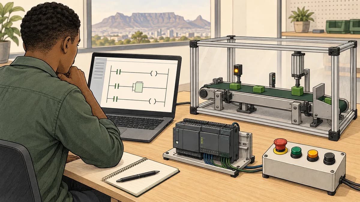
A ladder logic simulator should help you build an expression, predict its result and inspect what happens when you change the inputs. The right tool depends on your exercise: learning Boolean conditions, investigating execution order, practising timers or working in a specific vendor environment. Price and animated rung colours do not establish the scope on their own.
Use a small test project when comparing tools. Check supported instructions, how values are observed, what the documentation says about execution and how you can preserve the result. Automated feedback can be useful, but its conclusions are limited by the tests and model behind it.
This website is commercially connected to PLC Simulator. Its scan-cycle highlighting feature is an independent learning option to explore. We do not claim that it reproduces every instruction, task, I/O update or communication behaviour of every physical PLC.
What a ladder simulator helps you investigate
A ladder diagram represents program conditions and actions. A simulator can make those relationships visible while you practise. For a basic Boolean exercise, you should be able to change each input, predict the output and check every combination rather than relying on one successful run.
More advanced exercises need additional observations. A stateful block may depend on previous values. A timer needs a defined time base and reset rule. A sequence needs an initial state and transition conditions. The useful tool is the one that supports the particular behaviour you are trying to understand and explains its limits clearly.
Our ladder logic basics guide is a starting point for reading conditions. The broader PLC simulator guide discusses learning scope beyond ladder. This page focuses on evaluating a ladder environment and using a small execution-order experiment effectively.
Do not confuse a bit test with a physical contact
A ladder instruction can test whether a stored Boolean value is true or false. The symbol does not, by itself, tell you how a physical switch is constructed, wired or diagnosed. Establish the meaning of the variable before deciding what a particular condition represents.
Similarly, an ordinary output instruction can assign a data bit rather than directly prove the state of a physical device. Rockwell Automation's Output Energize instruction documentation describes setting or clearing a Boolean bit according to the rung condition for the listed controllers. That is specific instruction documentation, not a universal specification for every simulator.
Read the selected environment's instruction reference when building an exercise. Ordinary assignment, set/reset behaviour and retentive behaviour should not be treated as interchangeable simply because the diagram uses a coil-shaped symbol. Our contacts and coils reference provides a related learning route.

A practical simulator comparison checklist
| Capability | A useful check | What the result tells you |
|---|---|---|
| Boolean editing | Build and test a two-input expression | Whether the tool supports your basic notation and observation needs |
| Execution visibility | Follow an intermediate value through two assignments | Whether you can investigate the stated execution model |
| State inspection | Observe a value before and after an evaluation | Whether a change can be explained rather than guessed |
| Instruction documentation | Read the rule for the timer or counter you use | Which assumptions and limits apply to that instruction |
| Saving and revision | Reopen a named exercise version | Whether you can reproduce and review your work |
| Feedback | Compare a reported failure with a known input case | What the feedback actually checks |
A free editor may meet a simple learning objective well. An instructor can also assess a manually tested project without an automated grader. Conversely, a paid tool with many features may not support the target-specific behaviour you need. Compare the actual exercise and documentation rather than labelling whole categories as toys or professional trainers.
If a simulator advertises fault scenarios, ask what is changed in the model. A forced Boolean value, a simulated broken connection and a physical wiring fault are different things. A test can be educational without proving a real electrical fault response or a machine's safety performance.
Worked experiment: reading a value before or after it changes
Imagine a fictional learning application with two internal Boolean indicators. Source is a supplied input, Copied is an intermediate variable and Shown is another internal variable used for display. No physical output, machine command, interlock or safety function is involved.
The experiment compares two deliberately stated execution models. Within each model, assignments execute sequentially, and an assignment updates its variable immediately for the following statement. All three variables begin false. Source is supplied once at the start of each model pass and remains unchanged during that pass.
These assumptions define the experiment. They are not a claim that all PLC tasks, physical inputs or simulator displays behave identically. A vendor project would need its actual call order, instruction behaviour and observation timing checked separately.
Version A: copy first, then read the copy
Copied := Source
Shown  := Copied
At the end of each pass, Copied contains the supplied source value. Shown reads that newly assigned value during the same pass. Under this model, both values match Source when the pass finishes.
If Source changes from false to true, the first assignment sets Copied true. The second assignment then reads true and sets Shown true. There is no additional pass required by this particular ordering and these assumptions.
Version B: read the copy first, then update it
Shown  := Copied
Copied := Source
Now Shown reads the value that Copied held before this pass's update. The second assignment updates Copied, but does not go backwards and repeat the first assignment. At the end of the pass, Shown can therefore differ from the new source value.
This is an ordering effect in the defined model. It is not evidence of a slow network, a defective input module or a measured time delay. Its duration in seconds is not specified because the experiment supplies passes rather than a physical clock.

Predict both traces before running an implementation
Supply source values 0, 1, 1, 0, 0, 1. Both versions begin with Copied = 0 and Shown = 0. Here, 0 means false and 1 means true.
| Pass | Source | Version A copied | Version A shown | Version B copied | Version B shown |
|---|---|---|---|---|---|
| 1 | 0 | 0 | 0 | 0 | 0 |
| 2 | 1 | 1 | 1 | 1 | 0 |
| 3 | 1 | 1 | 1 | 1 | 1 |
| 4 | 0 | 0 | 0 | 0 | 1 |
| 5 | 0 | 0 | 0 | 0 | 0 |
| 6 | 1 | 1 | 1 | 1 | 0 |
The differences appear when the source changes. Pass three looks correct in both versions because the source has stayed true. A learner who tests only stable inputs may miss the ordering difference completely.
Pass four is especially useful. Version B's intermediate variable has already become false by the end of the pass, while its shown value remains true from the earlier read. Looking only at the final Copied value cannot explain when Shown read it; you need the execution order as well.
Translate the experiment into a supported ladder environment
If your environment supports ordinary Boolean tests and assignments with the stated behaviour, construct two simple rungs using internal variables. Keep the two versions separate and record the initial values. Observe the values at the points the tool actually exposes.
Do not substitute latch instructions for ordinary assignments. Do not introduce a second task, a physical I/O channel or another writer while trying to understand the initial experiment. Those additions change the assumptions and require their own analysis.
A tool may update its visual display less frequently than it evaluates a program. If you cannot observe an individual pass, use an appropriate supported stepping or trace facility, or record that the tool cannot demonstrate this detail directly. Do not claim a measured result from a screenshot that only shows a later stable state.
Check a different initial state
Repeat the first pass with Copied initially true and Source false. Version A ends with both copied and shown false. Version B ends with copied false and shown true, because it reads the initial true value before replacing it.
This case shows why initial conditions belong in a test record. A result that differs after reopening or resetting an exercise may reflect a different starting state rather than the same experiment producing inconsistent behaviour. Check what reset means in the selected tool instead of assuming it clears every variable.
The experiment does not test retention after power loss, download, warm restart or cold restart. Those operations can have target-specific rules. If they matter to your learning objective, select an appropriate vendor environment and document them separately.
Explain the result in a portfolio note
A useful note says: “In the sequential-assignment model, version B reads the previous copied value before updating it. The six-pass trace differs from version A on passes two, four and six.” It also states the initial values and the supplied input sequence.
An unhelpful note says only: “PLC scans are slow.” That conclusion is not established by the experiment. The exercise illustrates dependency and ordering; it does not measure execution speed or prove how an external device updates.
For a follow-up, move the displayed result to a direct assignment from Source and predict the new trace. Explain why that satisfies a different implementation structure while preserving the intended current-value result in this simple model. Keep the requirement clear before treating a code rearrangement as an improvement.
Multiple writers need an explicit review
The order experiment uses one writer for each destination in a pass. If you add another assignment to the same destination, you introduce another dependency that must be understood. Rockwell's OTE documentation specifically warns about unexpected operation when output tag operands are overwritten.
For a learning review, list every place that can write the variable and the conditions under which those places execute. Do not stop at the first matching coil you find. Also distinguish a value's internal assignment from when another task or display observes it.
Avoid reducing every platform to a universal slogan such as “last write wins.” The relevant question is which writes actually execute, in what context, with what instruction behaviour and when the value is read. The PLC scan-cycle guide is a related route, while the selected vendor's documentation is needed for its specific execution rules.

Timers, counters and comparisons: choose the next test deliberately
After Boolean expressions and simple dependencies, choose an instruction needed for your next exercise. For a timer, define the input condition, preset units, output condition and reset behaviour. Test before, at and after the threshold using the environment's documented time model.
For a counter, decide what event is counted and how reset or load behaves. A held true input is not necessarily the same as repeated transitions. Our timer reference and counter reference provide learning routes, but instruction details still need to match the tool you use.
Comparisons and data movement add another set of questions: data type, valid range, conversion and invalid input. Use the comparison reference and move-and-copy reference to organise those topics. Do not buy a tool from a long instruction list without checking the behaviours your exercises require.
There is no universal two-week ceiling for a simulator missing a particular feature. A restricted tool may support a focused course well. The limitation matters when your intended exercise requires something it cannot represent or observe accurately enough.
What an automated grader can and cannot establish
A grader can compare an implementation with selected expected outcomes and report a mismatch. Its usefulness depends on the quality of the specification, test cases and underlying model. A passing result supports those tested conditions; it is not a blanket proof of industrial suitability.
Ask whether the exercise includes cases that distinguish a common mistake from the intended solution. In the worked experiment, stable inputs alone would miss the changed-value behaviour. Tests involving both transitions and initial state reveal more than repeating the same successful condition.
An instructor or peer can also review a truth table, trace and explanation. Automated grading is one form of feedback, not the only way to learn. If a tool reports a failure, read the input conditions and expected outcome before changing the program simply to obtain a green score.
The PLC Simulator curriculum page is the relevant product route for investigating its learning exercises. Check the actual scenario and current access level; this page does not claim that every exercise uses the same number of tests or covers every possible fault.
Browser simulator versus vendor software
A browser tool can make introductory practice accessible without installing a complete engineering suite. Vendor software can be necessary when the objective is its actual project structure, instruction set or supported target behaviour. These are different learning needs and can be part of the same route.
CODESYS documents concrete differences between simulation and physical controller operation, including I/O and fieldbus limitations in simulation mode. That is a useful reminder to read explicit scope statements rather than assuming the word simulation guarantees complete physical equivalence.
If you need Siemens TIA Portal or Rockwell Studio 5000 experience, select learning in the appropriate environment and version. A familiar Boolean expression can help you understand the next tool, but does not establish direct project transfer or identical timing and communication behaviour.
Use the Siemens training guide or Allen-Bradley training guide to frame those platform questions. Keep independent simulator results labelled with the environment that actually produced them.

Choosing from South Africa: access, budget and practical follow-up
For home learning, try the actual editor on your device before committing to a course or subscription. Check readable diagrams, input controls, saving and the ability to inspect results. A browser-based product does not guarantee every feature on every phone, tablet or laptop.
For learners in Johannesburg, Cape Town, Durban or elsewhere, compare connectivity and scheduling requirements with your study conditions. Do not assume offline operation, negligible data use or uninterrupted saving during a power outage. Keep your own requirements and predictions available so you can continue paper-based study when needed.
Check the current PLC Simulator pricing if its paid features are relevant. Compare the specific access you need, rather than relying on an old lesson count or a fixed rand conversion. For classroom options, use the South African course price guide and request a current quotation.
Physical wiring and equipment diagnosis require appropriate practical instruction and authorisation. A simulated motor diagram or fault scenario is educational evidence within its model, not proof that an electrical circuit or safety function has been validated. Choose further training from the actual tasks you need to demonstrate.
Questions about ladder logic simulators
Can a free ladder logic simulator teach useful skills?
Yes, if it supports the exercise and gives you enough information to test and explain the result. Check its documentation and features. Price alone does not determine whether a tool has execution state, useful feedback or a suitable learning scope.
Why does my displayed bit lag after I move a rung?
One possibility is that the program reads an intermediate value before updating it, as in the worked model. Verify the actual call order, writers, initial conditions and observation timing. A lagging display can have other causes, so do not diagnose a real project solely from this example.
Does a green rung mean my program is correct?
It shows something about the tool's current evaluation or display state. Compare that observation with the requirement and test other relevant cases. One successful condition cannot establish all input combinations, transitions or startup behaviour.
Is simulated ladder identical to a physical PLC?
No universal equivalence should be assumed. Instructions, task scheduling, I/O, communications and restart behaviour can differ. Use the documentation for the chosen environment and label which behaviours you have actually tested.
Should I learn ladder before Structured Text?
Choose from your learning objective and target project. Ladder can make Boolean conditions approachable, while Structured Text can be convenient for calculations and data handling. The Structured Text learning guide provides a related route; this page does not claim that every South African employer expects the same language first.
How long does it take to become confident?
Use evidence rather than a promised number of weeks. Can you predict a result, build the exercise, test distinguishing cases and explain a failure? Repeat the unclear parts and obtain feedback. Simulator practice alone does not establish every skill or qualification required by a workplace.

Start with a comparison you can reproduce
Write the two assignment orders and predict the six-pass trace before opening a tool. Then use a supported environment to investigate the behaviour it exposes. Record initial values, input sequence, observations and any limits on what you could see.
That small experiment gives you a concrete basis for evaluating a ladder logic simulator. Continue with the instructions and feedback you need for the next exercise, and keep each conclusion tied to the conditions you actually tested.